
Switch User Manual

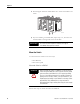
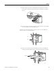


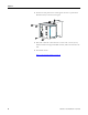


Table Of Contents
- 1783-UM002C-EN-E, Stratix 8000 Ethernet Managed Switches Hardware User Manual
- Preface
- Table of Contents
- 1 - Start
- 2 - Install the Switch
- Installation Guidelines
- Before You Begin
- Verify Package Contents
- Add Modules to the Switch
- Install the Switch
- Install or Remove the CompactFlash Card
- Set Up the Switch Initially with Express Setup
- Configure and Manage the Switch
- Reset the Switch to Factory Defaults
- Connect to the Switch Ports
- Verify Port Connectivity
- Verify Switch Operation
- Connect a Computer or a Terminal to the Console Port
- Run a Power-on Self-test (POST)
- Verify POST Results
- Disconnect Power
- Install and Remove SFP Modules
- Connect to SFP Modules
- 3 - Troubleshoot the Switch
- 4 - Cable and Connectors
- Index
- Back Cover

38 Publication 1783-UM002C-EN-P - April 2009
Chapter 2
Ground the Switch
Follow these steps to connect the switch to a protective ground.
1. Use a standard Phillips screwdriver or a ratcheting-torque screwdriver
with a Phillips head to remove the ground screw from the front panel of
the switch.
2. Store the ground screw for later use.
3. If your ground wire is insulated, use a wire stripping tool to strip the 5.3
mm
2
(10 AWG) ground wire to 12.7 mm (0.5 in.) ± 0.5 mm (0.02 in.).
4. Insert the ground wire into the ring terminal lug.
ATTENTION
For proper grounding, you must always connect the power
supply functional-ground screw when connecting the power
supply. You must provide an acceptable grounding path for each
device in your application. For more information on proper
grounding guidelines, refer to publication 1770-4.1
, Industrial
Automation Wiring and Grounding Guidelines.
ATTENTION
You must use the external grounding screw on the front of the
switch to ground the switch. Use a 5.3 mm
2
(10 AWG) ground
wire.
31789-M
12.7 mm (0.5 in.)