
Switch User Manual
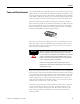
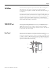
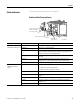
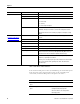
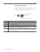
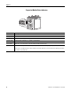

Table Of Contents
- 1783-UM002C-EN-E, Stratix 8000 Ethernet Managed Switches Hardware User Manual
- Preface
- Table of Contents
- 1 - Start
- 2 - Install the Switch
- Installation Guidelines
- Before You Begin
- Verify Package Contents
- Add Modules to the Switch
- Install the Switch
- Install or Remove the CompactFlash Card
- Set Up the Switch Initially with Express Setup
- Configure and Manage the Switch
- Reset the Switch to Factory Defaults
- Connect to the Switch Ports
- Verify Port Connectivity
- Verify Switch Operation
- Connect a Computer or a Terminal to the Console Port
- Run a Power-on Self-test (POST)
- Verify POST Results
- Disconnect Power
- Install and Remove SFP Modules
- Connect to SFP Modules
- 3 - Troubleshoot the Switch
- 4 - Cable and Connectors
- Index
- Back Cover
Publication 1783-UM002C-EN-P - April 2009 11
Chapter 1
Power and Relay Connector
You connect the DC power and alarm signals to the switch through two front
panel connectors. One connector provides primary DC power (supply A) and
the major alarm signal, and a second connector (supply B) provides secondary
power and the minor alarm signal. The two connectors are physically identical
and are in the upper left side of the front panel, as shown in the figure below.
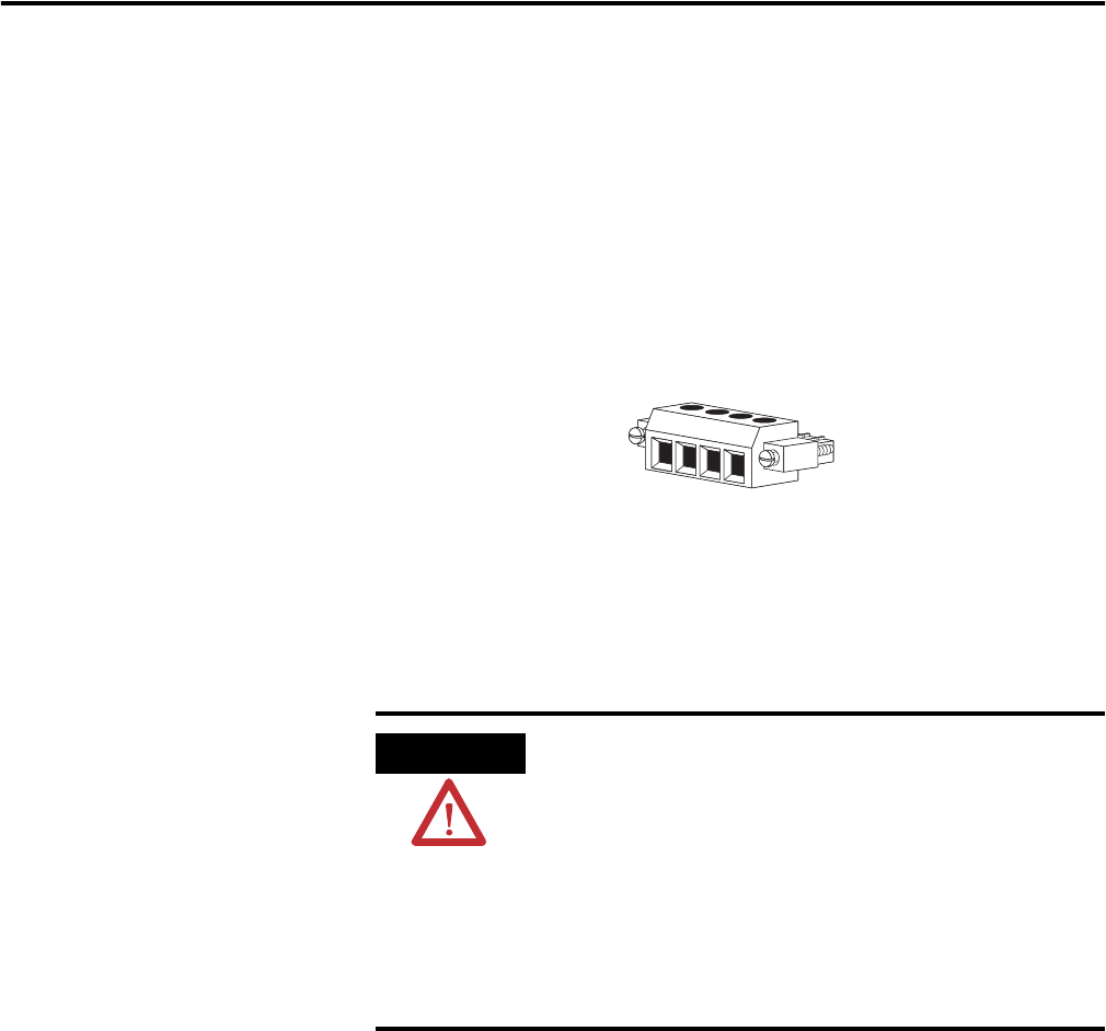
The switch accessory pack includes the mating power and relay connectors.
These connectors provide screw terminals for terminating the DC power and
alarm wire and plug into the power and relay receptacles on the front panel.
The positive DC power connection is labeled V, and the return is the adjacent
connection labeled RT, as shown in the figure below.
The switch can operate with a single power source or with dual power sources.
When both power sources are operational, the switch draws power from the
DC source with the higher voltage. If one of the two power sources fail, the
other continues to power the switch.
The power and relay connectors also provide an interface for two independent
alarm relays: the major alarm and the minor alarm. The relays can be activated
for environmental, power supply, and port status alarm conditions and can be
configured to indicate an alarm with either open or closed contacts. The relay
itself is normally open, so under power failure conditions, the contacts are
open. From the Command Line Interface (CLI), you can associate any alarm
condition with one alarm relay or with both relays.
Alarm relays often control an external alarm device, such as a bell or a light. To
connect an external alarm device to the relay, you must connect two relay
contact wires to complete an electrical circuit. Both alarm terminals on the
power and relay connector are labeled A. You can connect them without
regard to polarity.
WARNING
When you connect or disconnect the power and relay connector
with power applied, an electrical arc can occur. This could
cause an explosion in hazardous area installations. Be sure that
power is removed from the switch and alarm circuit. Be sure
that power cannot be accidentally turned on or verify that the
area is nonhazardous before proceeding.
Failure to securely tighten the power and relay connector
captive screws can result in an electrical arc if the connector is
accidentally removed.
RT
A
V
A
31783-M