
Switch User Manual
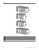
Table Of Contents
- 1783-UM002C-EN-E, Stratix 8000 Ethernet Managed Switches Hardware User Manual
- Preface
- Table of Contents
- 1 - Start
- 2 - Install the Switch
- Installation Guidelines
- Before You Begin
- Verify Package Contents
- Add Modules to the Switch
- Install the Switch
- Install or Remove the CompactFlash Card
- Set Up the Switch Initially with Express Setup
- Configure and Manage the Switch
- Reset the Switch to Factory Defaults
- Connect to the Switch Ports
- Verify Port Connectivity
- Verify Switch Operation
- Connect a Computer or a Terminal to the Console Port
- Run a Power-on Self-test (POST)
- Verify POST Results
- Disconnect Power
- Install and Remove SFP Modules
- Connect to SFP Modules
- 3 - Troubleshoot the Switch
- 4 - Cable and Connectors
- Index
- Back Cover
Publication 1783-UM002C-EN-P - April 2009 25
Chapter 2
Place the Switch
When determining where to place the switch, observe these guidelines
• Before attaching the switch to the network, first verify that the switch is
operational by powering it on and running POST. Follow the
procedures in the Verify Switch Operation section on page 62
.
• For 10/100 ports and 10/100/1000 ports, the cable length from a
switch to an attached device cannot exceed 100 m (328 ft).
• For 100BASE-FX fiber-optic ports, the cable length from a switch to an
attached device cannot exceed 2 km (6562 ft).
• Operating environment is within the ranges listed in the Stratix 8000
Ethernet Managed Switch Installation Instructions, publication
1783-IN005
.
• Clearance to front and rear panels meet these conditions:
– Front-panel status indicators can be easily read.
– Access to ports is sufficient for unrestricted cabling.
– Front-panel direct current (DC) power and relay connector is within
reach of the connection to the DC power source.
•
Airflow around the switch and through the vents is unrestricted. To
prevent the switch from overheating, provide the following minimum
clearances:
– Top and bottom: 105 mm (4.13 in.)
– Exposed side (not connected to the module): 90 mm (3.54 in.)
– Front: 65 mm (2.56 in.)
• Temperature surrounding the unit does not exceed 75 °C (167 °F)
• Cabling is away from sources of electrical noise, such as radios, power
lines, and fluorescent lighting fixtures.
ATTENTION
When the switch is installed in an industrial enclosure, the
temperature within the enclosure is greater than normal room
temperature outside the enclosure.
The temperature inside the enclosure cannot exceed 75
o
C
(167
o
F), the maximum ambient enclosure temperature of the
switch.