
Switch User Manual
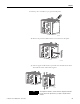
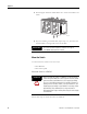
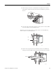
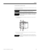
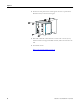
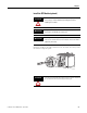
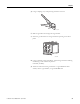
Table Of Contents
- 1783-UM002C-EN-E, Stratix 8000 Ethernet Managed Switches Hardware User Manual
- Preface
- Table of Contents
- 1 - Start
- 2 - Install the Switch
- Installation Guidelines
- Before You Begin
- Verify Package Contents
- Add Modules to the Switch
- Install the Switch
- Install or Remove the CompactFlash Card
- Set Up the Switch Initially with Express Setup
- Configure and Manage the Switch
- Reset the Switch to Factory Defaults
- Connect to the Switch Ports
- Verify Port Connectivity
- Verify Switch Operation
- Connect a Computer or a Terminal to the Console Port
- Run a Power-on Self-test (POST)
- Verify POST Results
- Disconnect Power
- Install and Remove SFP Modules
- Connect to SFP Modules
- 3 - Troubleshoot the Switch
- 4 - Cable and Connectors
- Index
- Back Cover
32 Publication 1783-UM002C-EN-P - April 2009
Chapter 2
4. Push the upper and lower module latches in to secure the module to the
switch.
5. If you are installing a second module, repeat steps 1...4, but secure the
second module to the right side of the first module.
Mount the Switch
You can mount the switch in one of two ways:
• On a DIN rail
• On a wall or panel
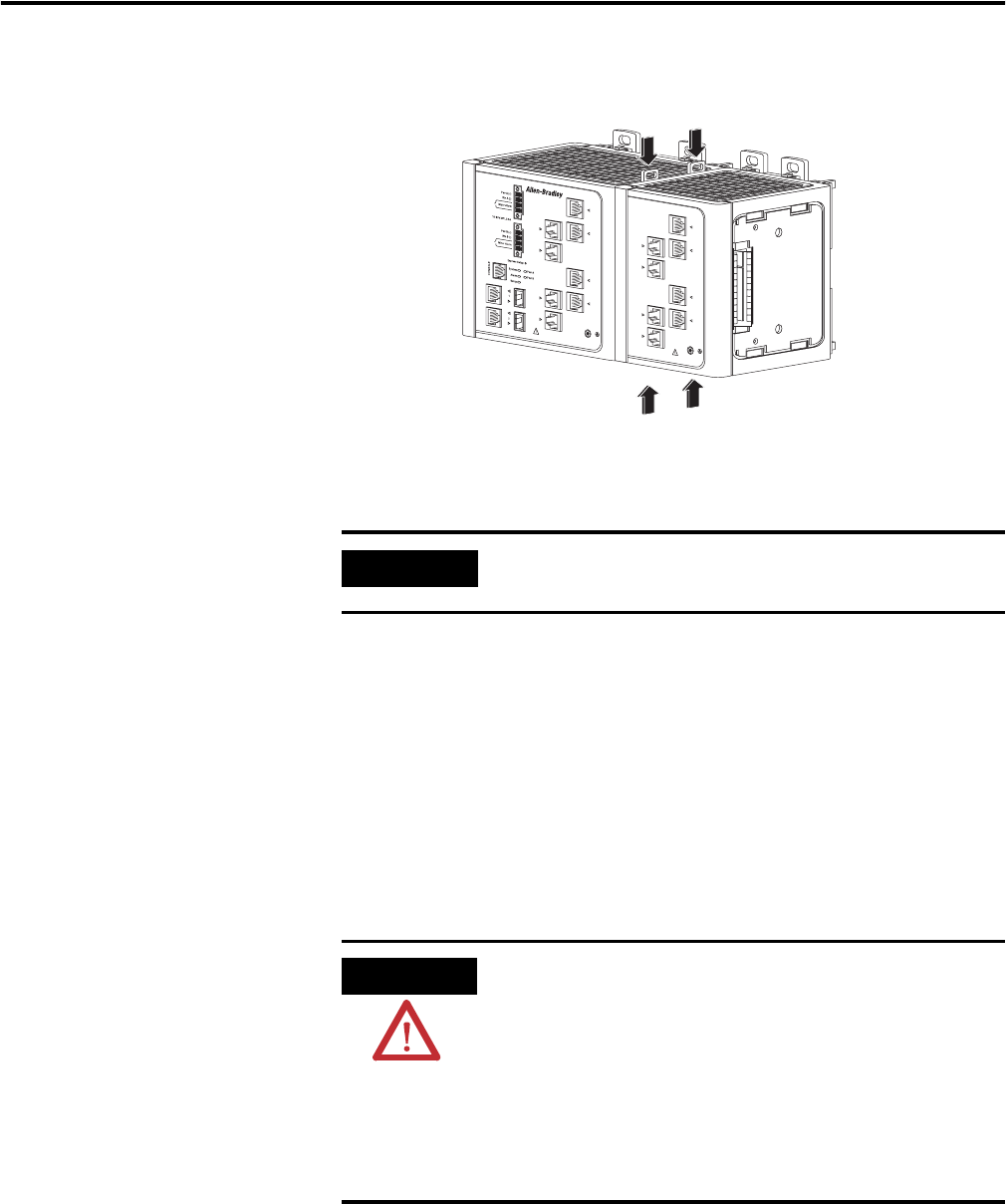
Mount the Switch on a DIN Rail
Follow these steps to mount the switch on a DIN rail.
IMPORTANT
You cannot install an expansion module to the right of
1783-MX08F fiber expansion module.
ATTENTION
When mounting the switch on a DIN rail, you can ground the
switch through the DIN rail to chassis ground. Use zinc plated
yellow-chromate steel DIN rail to assist in proper grounding.
The use of other DIN rail materials (for example, aluminum or
plastic)) that can corrode, oxidize, or are poor conductors, can
impede proper grounding. Secure DIN rail to mounting surface
approximately every 200 mm (7.8 in.) using end-anchors
appropriately and using a washer plate along the entire length
of the DIN rail.
31781-M