
Switch User Manual
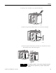
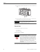
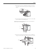
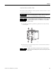
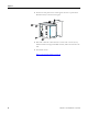
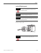
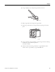
Table Of Contents
- 1783-UM002C-EN-E, Stratix 8000 Ethernet Managed Switches Hardware User Manual
- Preface
- Table of Contents
- 1 - Start
- 2 - Install the Switch
- Installation Guidelines
- Before You Begin
- Verify Package Contents
- Add Modules to the Switch
- Install the Switch
- Install or Remove the CompactFlash Card
- Set Up the Switch Initially with Express Setup
- Configure and Manage the Switch
- Reset the Switch to Factory Defaults
- Connect to the Switch Ports
- Verify Port Connectivity
- Verify Switch Operation
- Connect a Computer or a Terminal to the Console Port
- Run a Power-on Self-test (POST)
- Verify POST Results
- Disconnect Power
- Install and Remove SFP Modules
- Connect to SFP Modules
- 3 - Troubleshoot the Switch
- 4 - Cable and Connectors
- Index
- Back Cover
40 Publication 1783-UM002C-EN-P - April 2009
Chapter 2
Wire the DC Power Source
Follow these steps to prepare the DC power cable.
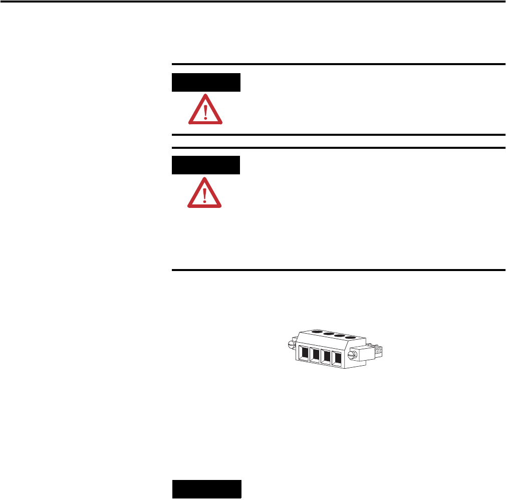
1. Locate the power and alarm relay connector.
2. Identify the positive and return DC power connections on the
connector.
The positive DC power connection is labeled V, and the negative DC power
connection is the adjacent connection labeled RT.
3. Measure a length of 0.82…0.52 mm
2
(18…20 AWG) copper wire long
enough to connect to the DC power source.
4. Using an 18-gauge wire-stripping tool, strip each of the two wires to 6.3
mm (0.25 in.) ± 0.5 mm (0.02 in.).
WARNING
Before performing any of the following procedures, make sure
that power is removed from the DC circuit or the area is
nonhazardous before proceeding.
ATTENTION
To comply with the CE Low Voltage Directive (LVD), this
equipment must be powered from a source compliant with the
safety extra low voltage (SELV) or protected extra low voltage
(PELV).
To comply with UL restrictions, this equipment must be
powered from a source compliant with Class 2 or Limited
Voltage/Current.
TIP
Connections labeled A are used for the alarm relay connectors.
RT
A
V
A
31783-M