
Switch User Manual
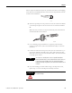
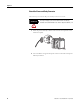
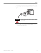
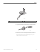
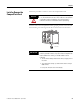
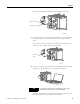
Table Of Contents
- 1783-UM002C-EN-E, Stratix 8000 Ethernet Managed Switches Hardware User Manual
- Preface
- Table of Contents
- 1 - Start
- 2 - Install the Switch
- Installation Guidelines
- Before You Begin
- Verify Package Contents
- Add Modules to the Switch
- Install the Switch
- Install or Remove the CompactFlash Card
- Set Up the Switch Initially with Express Setup
- Configure and Manage the Switch
- Reset the Switch to Factory Defaults
- Connect to the Switch Ports
- Verify Port Connectivity
- Verify Switch Operation
- Connect a Computer or a Terminal to the Console Port
- Run a Power-on Self-test (POST)
- Verify POST Results
- Disconnect Power
- Install and Remove SFP Modules
- Connect to SFP Modules
- 3 - Troubleshoot the Switch
- 4 - Cable and Connectors
- Index
- Back Cover
42 Publication 1783-UM002C-EN-P - April 2009
Chapter 2
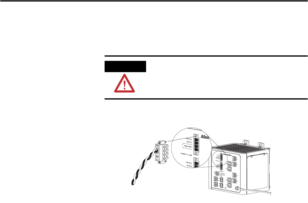
Attach the Power and Relay Connector
Follow these steps to connect the DC power and relay connector to the switch:.
1. Insert the power and relay connector into the Pwr A receptacle on the
switch front panel.
2. Use a screwdriver to tighten the captive screws on the sides of the power
and relay connector.
ATTENTION
The input voltage source of the alarm circuits must be an
isolated source and limited to less than or equal to 30V DC, 1 A.
VRTA A
31786-M