
Switch User Manual
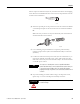
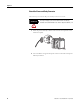
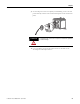
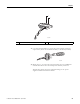
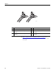
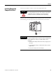
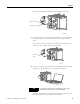
Table Of Contents
- 1783-UM002C-EN-E, Stratix 8000 Ethernet Managed Switches Hardware User Manual
- Preface
- Table of Contents
- 1 - Start
- 2 - Install the Switch
- Installation Guidelines
- Before You Begin
- Verify Package Contents
- Add Modules to the Switch
- Install the Switch
- Install or Remove the CompactFlash Card
- Set Up the Switch Initially with Express Setup
- Configure and Manage the Switch
- Reset the Switch to Factory Defaults
- Connect to the Switch Ports
- Verify Port Connectivity
- Verify Switch Operation
- Connect a Computer or a Terminal to the Console Port
- Run a Power-on Self-test (POST)
- Verify POST Results
- Disconnect Power
- Install and Remove SFP Modules
- Connect to SFP Modules
- 3 - Troubleshoot the Switch
- 4 - Cable and Connectors
- Index
- Back Cover
44 Publication 1783-UM002C-EN-P - April 2009
Chapter 2
Wire the External Alarms (Optional)
This procedure is optional.
The alarm relays on the switch are normally open. To connect an external
alarm device to the relays, you must connect two relay contact wires to
complete an electrical circuit. Because each external alarm device requires two
connections to a relay, the switch supports a maximum of two external alarm
devices.
To wire the switch to an external alarm device, follow these steps:
1. Measure two strands of twisted-pair wire (18...20 AWG) long enough to
connect to the external alarm device.
2. Use a wire stripper to remove the casing from both ends of each wire to
6.3 mm (0.25 in.) ± 0.5 mm (0.02 in.).
3. Insert the exposed wires for the external alarm device into the two
connections labeled A, as shown in the following figure.
ATTENTION
The input voltage source of the alarm circuits must be an
isolated source and limited to less than or equal to 50Vdc, 1A.
For wire connections to the power and relay connector, you
must use UL and CSA rated, style 1007 or 1569 twisted-pair
copper appliance wiring material (AWM) wire (such as Belden
part number 9318).
IMPORTANT
Do not strip more than 6.8 mm (0.27 in.) of insulation from the
wires. Stripping more than the recommended amount of wire
can leave exposed wire from the power and relay connector
after installation.