
Switch User Manual
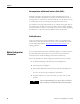
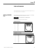
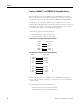
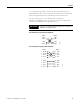
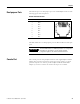
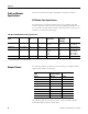
Table Of Contents
- 1783-UM002C-EN-E, Stratix 8000 Ethernet Managed Switches Hardware User Manual
- Preface
- Table of Contents
- 1 - Start
- 2 - Install the Switch
- Installation Guidelines
- Before You Begin
- Verify Package Contents
- Add Modules to the Switch
- Install the Switch
- Install or Remove the CompactFlash Card
- Set Up the Switch Initially with Express Setup
- Configure and Manage the Switch
- Reset the Switch to Factory Defaults
- Connect to the Switch Ports
- Verify Port Connectivity
- Verify Switch Operation
- Connect a Computer or a Terminal to the Console Port
- Run a Power-on Self-test (POST)
- Verify POST Results
- Disconnect Power
- Install and Remove SFP Modules
- Connect to SFP Modules
- 3 - Troubleshoot the Switch
- 4 - Cable and Connectors
- Index
- Back Cover
Publication 1783-UM002C-EN-P - April 2009 79
Chapter 4
Dual-purpose Ports
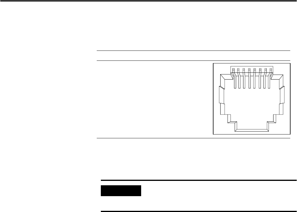
The Ethernet port on a dual-purpose port uses standard RJ45 connectors. The
following figure shows the pinouts.
Ethernet Port RJ45 Connector
The SFP module slot on a dual-purpose port uses SFP modules for fiber-optic
ports.
Console Port
The console port uses an 8-pin RJ45 connector. The supplied RJ45-to-DB-9
adapter cable is used to connect the console port of the switch to a console
personal computer. You need to provide an RJ45-to-DB-25 female DTE
adapter if you want to connect the switch console port to a terminal.
6
0915
231 45678Pin Label
1
2
3
4
5
6
7
8
TP0+
TP0-
TP1+
TP2+
TP2-
TP1-
TP3+
TP3-
IMPORTANT
The auto-MDIX feature is enabled by default. For configuration
information for this feature, see the switch software
configuration guide or the switch command reference.