4A COMPOUND MITER SAW PAG 5 ENG 14A SIERRA DE INGLETES COMPUESTA PAG 17 ESP 14A SCIE À ONGLET COMBINÉE PAG 29 FRE RK7135 RK7135 psm254mu 060602.
Thank you for purchasing a ROCKWELL power tool . We are confident that you will appreciate the quality of the product and you will be entirely satisfied with your purchase. Please read carefully the user safety and operating instructions on how to operate this product correctly within safety norms and regulations. Gracias por su compra de un producto ROCKWELL. Estamos seguros de que apreciará la calidad del producto y de que estará completamente satisfecho con su compra.
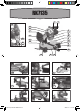
RK7135 1 2 20 19 18 21 22 23 17 3 16 5 4 6 15 7 14 8 9 10 13 12 11 A B C D E F G H I RK7135 psm254mu 060602.
J K L 1 2 3 B A A M N O 4 5 6 7 Mounting plate / Placa de montaje /Plaque de montage Loosen slightly / Afloje levemente /Desserrez quelque peu Q P 8 R 9 Blade/ Hoja /Lame Inner flange/ Arandela Interior /Rondelle intérieure S 10 Bolt-left hand thread/ Tornillorosca izquierda/ Boulon de serrage-filets à gauche 11 12 Outer Flange/ Arandela exterior/Rondelle extérieure 13 14 15 16 17 18 19 20 21 22 23 RK7135 psm254mu 060602.
14A COMPOUND MITER SAW ENG COMPONENT LIST 1 TRIGGER SWITCH 2 HANDLE 3 MOTOR HOUSING 4 SAW BLADE 5 RETRACTABLE SAFETY GUARD 6 FENCE 7 TABLE EXTENSION RAIL (ON BOTH SIDES) 8 MITER TABLE 9 MITER DETENT LEVER 10 MITER LOCK HANDLE 11 THROAT PLATE 12 MITER SCALE 13 MOUNTING HOLES (4) 14 VERTICAL CLAMP LOCKING SCREW 15 VERTICAL CLAMP 16 MITER ARM LOCK PIN 17 RETRACTABLE SAFETY GUARD ACTUATOR 18 SAFETY GUARD MOUNTING PLATE 19 UPPER BLADE GUARD 20 BLADE LOCK LEVER 21 DUST E
14A COMPOUND MITER SAW ENG ACCESSORIES Blade wrench Work clamp Miter lock handle Dust bag Extension rails 10”x40T carbide tipped saw blade 1 1 1 1 1 1 pc pc pc pc set pc We recommend that you purchase your accessories from the same store that sold you the tool. Use good quality accessories with a well-known brand name. Choose the type according to the work you intend to undertake. Refer to the accessory packaging for further details. Store personnel can assist you and offer advice.
14A COMPOUND MITER SAW Loose clothes, jewelry, or long hair can be caught in moving parts. Keep handles dry, clean and free from oil and grease. Rubber gloves and nonskid footwear are recommended when working outdoors. - AVOID ACCIDENTAL STARTING. BE SURE SWITCH IS “OFF” BEFORE PLUGGING IN. Carrying tools with your finger on the switch or plugging in tools that have the switch “ON” invites accidents. Do not use a tool if the power switch does not turn it “ON” and “OFF”.
14A COMPOUND MITER SAW 2. 3. 4. 5. 6. 7. 8. 9. 10. 11. 12. 13. 14. 15. 16. 17. 18. 19. INSTRUCTIONS. A machine incorrectly assembled can cause serious injury. YOUR MITER SAW MUST BE BOLTED SECURELY TO A STAND OR WORKBENCH. In addition, if there is any tendency for the miter saw to tip over or move during certain operations such as cutting long, heavy boards, use an auxiliary support NEVER START THE TOOL WITH THE WORK-PIECE AGAINST THE BLADE.
14A COMPOUND MITER SAW ENG SYMBOLS Read the manual Warning Use inside only Do not expose to rain or water Do not burn Wear safety goggles, dust mask and ear protection Double insulation EXTENSION CORDS When using an extension cord, be sure to use one heavy enough to carry the current your product will draw. An undersized cord will cause a drop in line voltage, resulting in loss of power and overheating.
14A COMPOUND MITER SAW TECHNICAL DATA Voltage: Rated Current: No load speed: Miter Capacity: Bevel Capacity: Blade Diameter: Blade Bore: Maximum Cutting Capacity: Miter 0º/Bevel 0º : Miter 0º/Bevel 45º : Miter 45º/Bevel 0º : Miter 45º/Bevel 45º: Protection Class: Weight: 120V~60Hz 14A 5200 rpm 0º - 45º (left & right ) 0º - 45º 10” 5/8” 4”x3-1/2” 4”x2” 2-3/4”x3-1/2” 2-3/4”x2” / II 28.6Ibs OPERATING INSTRUCTIONS NOTE: Before using the tool, read the instruction book carefully. 1.
14A COMPOUND MITER SAW WARNING: Never use tool without a functioning blade guard. Serious personal injury can result. 3. Miter LOCK HANDLE The miter lock handle (10) securely locks your saw at the desired miter angle. 4. SPINDLE LOCK BUTTON The spindle lock button (20) on your saw allows you to lock the spindle that keeps the blade in your saw from rotating. Only depress and hold the lock button when installing, changing or removing the blade. 5.
14A COMPOUND MITER SAW TRAVEL PIVOT ADJUSTMENT Your saw arm should rise completely to the up position by itself. To avoid risk of personal injury, if your saw arm does not rise by itself or if there is play in the pivot joints, have your saw serviced by qualified person. BEVEL PIVOT ADJUSTMENT Your compound miter saw arm should bevel easily by loosening the bevel lock knob (22) and tilting the saw arm to the left. 9.
14A COMPOUND MITER SAW bench. Never operate your miter saw on the floor or in a crouched position. Failure to heed this warning could result in serious personal injury. WARNING: When using a hold-down clamp to secure the work-piece, clamp work-piece on one side of the blade only. The work-piece MUST remain free on one side of the blade to prevent the blade from binding in the work-piece.
A COMPOUND MITER SAW with zero on the miter scale. f. Release the miter lock plate. g. Tighten the miter lock handle securely. NOTE: You can quickly locate 0° by releasing the lock plate as you rotate the control arm. The lock plate will seat itself in one of the positive stop notches, located in the miter table frame. WARNING: To avoid serious personal injury, ALWAYS tighten the miter lock handle securely BEFORE making a cut.
14A COMPOUND MITER SAW the miter table frame. g. Tighten the miter lock handle securely. WARNING: To avoid serious personal injury, ALWAYS tighten the miter lock handle securely BEFORE making a cut. Failure to do so could result in movement of the control arm or miter table while making a cut. The 45° triangle on the miter fence provides for the maximum clearance required for adjusting the miter saw angle when making a bevel or compound cut. h.
14A COMPOUND MITER SAW flashing in the ventilation slots, this is normal and will not damage your power tool. WARRANTY LIMITED 30-DAY EXCHANGE POLICY During the first 30 days after date of purchase, you may exchange a tool which does not work properly due to defects in materials or workmanship by returning the power tool to the retailer where it was purchased. To receive a replacement power tool, you must present a dated proof of purchase and return all original equipment packaged with the original product.
14A SIERRA DE INGLETES COMPUESTA ESP LISTA DE PARTES 1 GATILLO 2 MANGO 3 CAJA DEL MOTOR 4 HOJA DE SIERRA 5 PROTECTOR INFERIOR DE LA HOJA (RETRÁCTIL) 6 BORDE 7 EXTENSIONES DE LA MESA 8 MESA DE INGLETE 9 PALANCA DE TRABA DE INGLETE 10 MANGO DE TRABA DE INGLETE 11 PLACA DE GARGANTA (ACCESORIO DE INSERCIÓN PARA LA SEPARACIÓN DE CORTE) 12 ESCALA DE INGLETE 13 AGUJEROS DE MONTAJE DE LA SIERRA (4) 14 TORNILLO PARA SUJETAR LA PIEZA DE TRABAJO 15 PRENSA PARA LA PIEZA DE TRABAJO 16 CL
14A SIERRA DE INGLETES COMPUESTA ACCESORIOS Llave de sierra Prensa Mango de traba para ingletes Bolsa recolectora de polvo Juego de rieles extensibles Hoja de sierra de 10”x40T 1 1 1 1 2 1 Le recomendamos que compre todos los accesorios en la tienda donde adquirió la herramienta. Use accesorios de buena calidad estampado con una marca bien conocida. Seleccione los que más convengan al trabajo que intenta hacer. Consulte el empaque de los accesorios para obtener más detalles.
14A SIERRA DE INGLETES COMPUESTA - LAS HERRAMIENTAS CONECTADAS A TIERRA DEBEN ESTAR ENCHUFADAS EN UN TOMACORRIENTE QUE ESTÉ INSTALADO CORRECTAMENTE Y CONECTADO A TIERRA DE ACUERDO CON TODOS LOS CÓDIGOS Y ORDENANZAS VIGENTES. Nunca saque la pata de conexión a tierra o modifique el enchufe de ninguna manera. No use enchufes adaptadores. Consulte a un electricista capacitado si tiene dudas para asegurar que el tomacorriente esté correctamente conectado a tierra.
14A SIERRA DE INGLETES COMPUESTA tienen menos probabilidades de atascarse y son más fáciles de controlar. Toda alteración o modificación constituye un uso incorrecto y puede tener como resultado una situación peligrosa. - COMPRUEBE LA DESALINEACIÓN O EL ATASCO DE LAS PIEZAS MÓVILES, LA RUPTURA DE PIEZAS Y CUALQUIER OTRA SITUACIÓN QUE PUEDA AFECTAR EL FUNCIONAMIENTO DE LAS HERRAMIENTAS. SI LA HERRAMIENTA ESTÁ DAÑADA, HÁGALA ARREGLAR ANTES DE USARLA.
14A SIERRA DE INGLETES COMPUESTA de trabajo o cambiar el ángulo de la hoja. 15. NUNCA PONGA LAS MANOS ALREDEDOR NI DETRÁS DE LA HOJA DE SIERRA. 16. REEMPLACE EL INSERTO DE LA MESA CUANDO SE GASTE. 17. NO CORTE PIEZAS PEQUEÑAS SIN SUJETARLAS. MANTENGA LAS MANOS A 6” O MÁS LEJOS DE LA HOJA. 18. DEJE QUE EL MOTOR ALCANCE SU VELOCIDAD MÁXIMA ANTES DE COMENZAR EL CORTE. 19. CONSERVE ESTAS INSTRUCCIONES. Consúltelas con frecuencia y úselas para enseñarles a las otras personas que podrían usar esta herramienta.
14A SIERRA DE INGLETES COMPUESTA DATOS TÉCNICOS Voltios: 120V~60Hz Corriente nominal: 14A Velocidad sin carga: 5200rpm Capacidad de inglete: 0º- 45º (izquierda y derecha) Capacidad de biselado: 0º - 45º Diámetro de hoja: 10” Mandrilado: 5/8” Capacidad máxima de corte: Inglete 0º/Biselado 0º: 3-1/2”x4” Inglete 0º/Biselado 45º: 2”x4” Inglete 45º/Biselado 0º: 3-1/2”x2-3/4” Inglete 45º/Biselado 45º: 2”x2-3/4” Clase de protección: / II Peso: 28.
14A SIERRA DE INGLETES COMPUESTA FRENO ELÉCTRICO Esta herramienta viene equipada con un freno eléctrico de hoja. Si la herramienta no detiene rápidamente la hoja luego de soltar el gatillo, hágala revisar por una persona calificada. El sistema de freno de la hoja no sustituye la cubierta de seguridad. ADVERTENCIA: Nunca use la herramienta si la cubierta de protección no funciona. Puede causar daños personales graves. 3.
14A SIERRA DE INGLETES COMPUESTA RANURA DE LA BASE Para su comodidad, la ranura del plato de la base ha sido cortada en la fábrica para permitir que la hoja pase sin tocarla en cualquier ángulo desde 0º a 45º. AJUSTE DEL PIVOTE NOTA: Estos ajustes vienen hechos de fábrica y no se requiere ninguna modificación bajo condiciones normales. AJUSTE DEL VIAJE DEL PIVOTE El brazo de su sierra debe levantarse completamente hasta arriba de todo por si mismo.
14A SIERRA DE INGLETES COMPUESTA 10. CORTANDO CON SU SIERRA DE INGLETES Use su sierra únicamente para los fines indicados a continuación: - Corte transversal de madera o plástico. - Corte transversal de ingletes, juntas, etc. Para marcos de cuadros, mormuras, marcos de puertas y juntas delicadas. NOTA: La hoja incluida con esta sierra es ideal para cortar una gran variedad de maderas. ADVERTENCIA: Antes de empezar cualquier operación de corte, fije o atornille su sierra a un banco de trabajo.
14A SIERRA DE INGLETES COMPUESTA PARA HACER CORTES BISELADOS CON SU SIERRA a. Desenchufe la sierra. ADVERTENCIA: Para evitar heridas personales, desenchufe SIEMPRE la unidad ANTES de colocar partes, hacer ajustes o cambiar las hojas. b. Saque la clavija de traba y levante el brazo de la sierra hasta arriba de todo. c. Afloje la traba de ajuste de ingletes. Gire el mango de traba de ingletes media vuelta hacia la izquierda para aflojarlo. d. Presione la palanca de traba de inglete para desengancharla. e.
14A SIERRA DE INGLETES COMPUESTA c. Afloje la traba de ajuste de ingletes (10). Gire el mango de traba de ingletes media vuelta hacia la izquierda para aflojarlo. d. Levante la palanca de traba de la base (9). e. Rote el brazo de control hasta que la referencia quede alineada con el ángulo deseado de la escala. f. Suelte la palanca de traba. NOTA: Puede encontrar rápidamente los 0°, 15°, 22,5°, 30° y 45º hacia la izquierda o hacia la izquierda o derecha soltando la palanca mientras rota el brazo de control.
14A SIERRA DE INGLETES COMPUESTA MANTENGA LAS HERRAMIENTAS CON CUIDADO Conserve las herramientas afiladas y limpias para que funcionen mejor y con más seguridad. Inspeccione periódicamente los cables de las herramientas y si están dañados hágalos reparar por un centro de servicio autorizado. Su herramienta no requiere lubricación ni mantenimiento adicional. No posee piezas en su interior que puedan ser reparadas por el usuario. Nunca emplee agua o productos químicos para limpiar su herramienta.
14A SCIE À ONGLET COMBINÉE FRE LISTE DES ÉLÉMENTS 1 INTERRUPTEUR MARCHE/ARRÊT 2 POIGNÉE 3 BOÎTIER DE MOTEUR 4 LAME DE SCIE 5 GARDE LAME RÉTRACTABLE (INFÉRIEUR) 6 GUIDE 7 RALLONGES DE LA TABLE 8 TABLE À ONGLETS 9 LEVIER DE BLOCAGE/DÉBLOCAGE D’ONGLET 10 BOUTON DE VERROUILLAGE D’ONGLET 11 PASSE-LAME (TRAIT DE SCIE) 12 ÉCHELLE D’ONGLETS 13 TROUS DE FIXATION DE LA SCIE (4) 14 VIS DE SERRAGE DE LA SERRE DE MAINTIEN DE L’OUVRAGE 15 SERRE DE MAINTIEN DE L’OUVRAGE 16 GOUPILLE DE VERR
14A SCIE À ONGLET COMBINÉE FRE ACCESSOIRES Clé de lame Pince de travail Poignée de verrouillage d’onglet Sac à poussièe Jeu de rails extensibles Lame de scie de 10pox40T 1 1 1 1 2 1 Nous vous recommandons d’acheter tous vos accessoires du même magasin qui vous a vendu l’outil. N’utilisez que des accessoires de bonne qualité de marque renommée. Choisissez le type d’outil approprié au travail que vous désirez entreprendre. Pour de plus amples renseignements, consultez l’emballage de l’accessoire.
14A SCIE À ONGLET COMBINÉE FRE vous n’êtes pas certain que la prise de courant est correctement mise à la terre, adressez-vous à un électricien qualifié. En cas de défaillance ou de défectuosité électrique de l’outil, une mise à la terre offre un trajet de faible résistance à l’électricité qui autrement risquerait de traverser l’utilisateur. avec l’outil de coupe. - TENEZ LES MAINS À L’ÉCART DES ARRÊTES TRANCHANTES ET DES PIÈCES EN MOUVEMENT.
14A SCIE À ONGLET COMBINÉE mais être dangereux avec un autre. - UTILISEZ L’OUTIL APPROPRIÉ À LA TÂCHE À ACCOMPLIR. Ne forcez pas l’outil ni l’accessoire en tentant d’effectuer une tâche pour laquelle ils n’ont pas été conçus. - DIRECTION DE L’ALIMENTATION DU MATÉRIEL. N’alimentez les pièces à ouvrer que dans le sens contraire de la rotation de la lame ou du couteau (de l’avant vers arrière de l’outil lorsque la lame est correctement montée.
14A SCIE À ONGLET COMBINÉE • • • • TEL QUE PONÇAGE, SCIAGE, MEULAGE, PERÇAGE ET AUTRES TRAVAUX DU BÂTIMENT PEUVENT CRÉER DES POUSSIÈRES CONTENANT DES PRODUITS CHIMIQUES QUI SONT DES CAUSES RECONNUES DE CANCER, DE MALFORMATION CONGÉNITALE OU D’AUTRES PROBLÈMES REPRODUCTIFS.
14A SCIE À ONGLET COMBINÉE DONNÉES TECHNIQUES Tension : 120V~60Hz Ampérage nominal: 14A Vitesse à vide : 5200 tr/min Plage d‘onglets: 0º - 45º (gauche/droit) Plage de chanfreins: 0º - 45º Diamètre de lame: 10 po Alésage de la lame: 5/8 po Capacité maximale de coupe : Onglet 0º/Chanfrein 0º: 3-1/2x4 po Onglet 0º/Chanfrein 45º: 2x4 po Onglet 45º/Chanfrein 0º: 3-1/2x2-3/4 po Onglet 45º/Chanfrein 45º: 2x2-3/4 po Classe de protection: /II Poids: 28.
14A SCIE À ONGLET COMBINÉE qualifié. Le frein de lame n’est pas un substitut du garde. AVERTISSEMENT: N’utilisez jamais l’outil sans gardes, des accidents causant de graves blessures pourraient alors survenir. 3. POIGNÉE DE BLOCAGE D’ONGLET La poignée de blocage d’onglet (10) verrouille de façon sûre votre scie à l’angle d’onglet désiré. 4. BOUTON DE BLOCAGE DE L’ARBRE Le bouton de blocage de l’arbre (20) de votre scie permet de bloquer l’arbre prévenant sa rotation lors du changement de lame.
14A SCIE À ONGLET COMBINÉE RÉGLAGE DU DÉPLACEMENT DU PIVOT Votre bras de scie doit remonter de lui-même. Afin d’éviter un risque d’accident, si ce n’est pas le cas, ou s’il y a du jeu dans le pivot, présentez votre scie au Service Après-Vente avant d’utiliser la machine. RÉGLAGE DU PIVOT D’INCLINAISON Votre bras de scie à onglet doit s’incliner aisément en desserrant le bouton de blocage d’inclinaison (22) et en inclinant la tête à gauche. 9. CHANGEMENT DE LAME (voir Figs.
14A SCIE À ONGLET COMBINÉE NOTE: la lame incluse avec cette scie est idéale pour une grande variété de coupes dans le bois. AVERTISSEMENT: AVANT de commencer toute coupe, fixez la scie sur un établi. Ne faites JAMAIS fonctionner la scie au sol ou dans une position basse. Le non respect de cette mise en garde peut entraîner un accident. AVERTISSEMENT: Lors de l’emploi de serre-joints pour tenir la pièce, ne serrez la pièce que d’un coté. La pièce doit être libre d’un coté afin d’éviter tout coincement.
14A SCIE À ONGLET COMBINÉE g. Serrez fermement la poignée de blocage d’onglet. NOTE: Vous pouvez rapidement trouver la position 0° en relâchant la plaque de blocage en tournant le bras. La plaque de blocage se positionnera d’ellemême dans une des positions indexées placées dans la table. AVERTISSEMENT: Pour éviter tout accident grave, serrez TOUJOURS la poignée de blocage d’onglet AVANT de faire une coupe. Ne pas respecter cette consigne peut entraîner un mouvement du bras ou de la table lors de la coupe.
14A SCIE À ONGLET COMBINÉE consigne peut entraîner un mouvement du bras ou de la table lors de la coupe. Le triangle à 45° sur le guide donne le maximum d’espace nécessaire pour ajuster l’angle d’onglet lors d’une coupe inclinée ou composée. h. Desserrez le bouton de blocage d’inclinaison (22) et déplacez le bras vers la gauche jusqu’à l’inclinaison désirée. L‘angle d’inclinaison peut être réglé entre 0° et 45°. i. Alignez l’index sur de l’angle désiré. j.
14A SCIE À ONGLET COMBINÉE FRE GARANTIE en toutes lettres dans la présente garantie. POLITIQUE D’ÉCHANGE LIMITÉE DE TRENTE (30) JOURS Un outil qui ne fonctionne pas correctement à cause d’un défaut de pièce ou de main-d’œuvre est échangeable durant les trente (30) premiers jours après la date d’achat en rapportant l’outil au détaillant où il a été acheté. Pour obtenir un outil de remplacement vous devez présenter une preuve d’achat datée et retourner l’outil dans son emballage original.
RK7135 psm254mu 060602.
RK7135 psm254mu 060602.
RK7135 psm254mu 060602.
RK7135 psm254mu 060602.