power your future℠ ROCFORCE Parallel Redundancy On‐Line UPS Tower and Rack‐Mount convertible User Manual 4,500 VA 6,000 VA 8,000 VA 10,000 VA
ROCPOWER – ROCFORCE ‐ Parallel Redundancy On‐Line ‐ user manual Table of Contents IMPORTANT SAFETY INSTRUCTIONS....................................................................................... 3 Chapter 1................................................................................................................................ 6 Front Panel Function Explanations.............................................................................................. 6 Rear Panel Explanation..................
ROCPOWER – ROCFORCE ‐ Parallel Redundancy On‐Line ‐ user manual IMPORTANT SAFETY INSTRUCTIONS PLEASE, SAVE THESE INSTRUCTIONS This manual contains important instructions that should be followed during unpacking, installation and maintenance of the UPS and batteries.
ROCPOWER – ROCFORCE ‐ Parallel Redundancy On‐Line ‐ user manual • • Servicing of batteries should be performed or supervised by persons knowledgeable about batteries and the required precautions. Keep unauthorized personnel away from batteries. When replacing batteries, replace with the same number and type. CAUTION – Do NOT dispose of battery or batteries in a fire. The battery may explode. CAUTION – Do NOT open or mutilate the battery or batteries. Released electrolyte is harmful to the skin and eyes.
ROCPOWER – ROCFORCE ‐ Parallel Redundancy On‐Line ‐ user manual CAUTION ‐ To reduce the risk of fire, connect the UPS unit input to a circuit with a 40 amperes rating in accordance with the National Electric Code, ANSI/NFPA 70. Use No. 10 AWG, 60°C copper wire and 22.1 lb‐in Torque force when connecting to terminal block.
ROCPOWER – ROCFORCE ‐ Parallel Redundancy On‐Line ‐ user manual CHAPTER 1 Panel explanation Front Panel Function Explanations LCD Display Green LED steadily lights up to indicate that the utility input voltage is in range. The LED flashes to indicate that the utility input voltage is within the acceptable range. Green LED lights up to indicate Bypass Input is normal. Green LED lights up to indicate the UPS has the capability to run under Redundancy Mode.
ROCPOWER – ROCFORCE ‐ Parallel Redundancy On‐Line ‐ user manual Rear Panel Explanation A Terminal Resistor for Parallel function B RS232 Port C External Battery Connector D Utility Input Breaker E CAN Bus Connection Port for Parallel System F Maintenance Bypass Switch and Galvanic Tx.
ROCPOWER – ROCFORCE ‐ Parallel Redundancy On‐Line ‐ user manual DCE(Dry Contact plus EPO), as well as SNMP/ card. However, the R2E card, RSE card and USE card cannot be used simultaneously. The bundled software for the UPS is compatible with many operating systems such as Windows 98, & 2000, ME, NT , XP and Vista. For other applications like Novell, NetWare, UNIX, Linux, please contact your local distributor for a proper solution.
ROCPOWER – ROCFORCE ‐ Parallel Redundancy On‐Line ‐ user manual CHAPTER 2 Check the unit in its packing container and after removal, but before installation, for any obvious problems. Retain the packing material for future use. Unpacking CAUTION: Please be careful when lifting the shipping container or the UPS. These items are heavy. Improper lifting or movement may cause personal injuries or property damage. • • • Take the UPS out of the packing material. Retain it for future use.
ROCPOWER – ROCFORCE ‐ Parallel Redundancy On‐Line ‐ user manual Package contents for the UPS with isolation transformer but without Maintenance Bypass Switch: • Standard Package plus 3pcs No. 10 AWG, 60°C copper wire (2pcs 12 inches long NEMA L5‐30P and 1pcs 12 inches long NEMA L5‐30R are to be used at the input/output terminal block of the UPS. Please refer to page 14 number 2 for installation diagram.
ROCPOWER – ROCFORCE ‐ Parallel Redundancy On‐Line ‐ user manual input breaker on front panel. Repeat this procedure every two (2) months in a high temperature environment.
ROCPOWER – ROCFORCE ‐ Parallel Redundancy On‐Line ‐ user manual CHAPTER 3 Installation Installation of Casters Cover Tower installation steps Power Module + Battery Module Step1: Installation Foot Cover and Power S3 Step2: Installation Power Module and Battery S3 S1 A3 12
ROCPOWER – ROCFORCE ‐ Parallel Redundancy On‐Line ‐ user manual Power Module + Isolation Transformer Module+ Battery Module Step1: Installation Power, Isolation Transformer and Battery S3 Rack installation steps Power Module + Battery Module Step1: Installation Ear B1 B2 S4 B1 B3 S4 13
ROCPOWER – ROCFORCE ‐ Parallel Redundancy On‐Line ‐ user manual Step2: Installation Ear Cover to Power, Isolation Transformer and Battery Module S3 Step3: Installation Rail to Rack S3 14
ROCPOWER – ROCFORCE ‐ Parallel Redundancy On‐Line ‐ user manual Step 4: Installation Battery Module to Rail Power Module+ Isolation Transformer Module+ Battery Module Step 1: Installation Isolation Transformer Module to Rail 15
ROCPOWER – ROCFORCE ‐ Parallel Redundancy On‐Line ‐ user manual Step 2: Installation Power Module to Rack 16
ROCPOWER – ROCFORCE ‐ Parallel Redundancy On‐Line ‐ user manual Terminal Block Explanation ● L12‐N1: the terminal for the Utility Input provides the power source when the UPS is working in Utility Mode. ● G1: the terminal for the UPS Input Ground. ● L21‐N22: the terminals for the UPS Output. ● G2: the terminal for the UPS Output Ground. Remarks: 1. When the Battery Bank is installed: G + G + G + 2.
ROCPOWER – ROCFORCE ‐ Parallel Redundancy On‐Line ‐ user manual CHAPTER 4 Operational Test Start Up in Normal Mode Open the terminal block cover on the rear panel. Before starting the installation, please ensure that the ground is connected properly. Ensure that the utility breaker and UPS input breaker are in the OFF position. Ensure that the utility voltage matches the input voltage of the UPS. Connect the utility separately to the terminal blocks of UPS Utility and Bypass Inputs.
ROCPOWER – ROCFORCE ‐ Parallel Redundancy On‐Line ‐ user manual message, it means the pre‐startup of the UPS is successful and the charger begins to charge the batteries. Press the UPS ON Switch for approximately three (3) seconds. The Buzzer will sound twice and the LCD display will change from drawing B to drawing C. C The UPS is now in Self‐Test Mode. The LCD display will change from drawing C to drawing D and remain for approximately four (4) seconds under Battery Mode.
ROCPOWER – ROCFORCE ‐ Parallel Redundancy On‐Line ‐ user manual F * It shows “220VAC” in Utility Input. If the Self‐Test is unsuccessful, the LCD display will change from Drawing D to drawing E2. An error code or error status will be shown on the screen. The start‐up operation of the UPS is completed. Ensure that the UPS is plugged onto the wall outlet and charged for at least 8 hours.
ROCPOWER – ROCFORCE ‐ Parallel Redundancy On‐Line ‐ user manual H * It shows Utility Input is “0” and Utility Abnormal.
ROCPOWER – ROCFORCE ‐ Parallel Redundancy On‐Line ‐ user manual Check Measured Values & Figures detected by UPS If you would like to check the measured values and figures detected by the UPS, please use and “scroll up” key pads.
ROCPOWER – ROCFORCE ‐ Parallel Redundancy On‐Line ‐ user manual L * It shows UPS Output Voltage. M * It shows UPS Output Frequency. N * It shows UPS Output Load Level (%). O * It shows Battery Voltage. P * It shows UPS Inner Temperature.
ROCPOWER – ROCFORCE ‐ Parallel Redundancy On‐Line ‐ user manual UPS Default Data and Special Function Execution After the UPS completely starts up, press the drawing Q1. key pad to change the LCD display screen to Q1 * It shows buzzer ON. Q2 * It shows buzzer OFF. Press the key pad to scroll down the screen and check the UPS settings.
ROCPOWER – ROCFORCE ‐ Parallel Redundancy On‐Line ‐ user manual R2 * It shows self‐test is ON. S1 * It shows Bypass Voltage is 195VAC‐260VAC. S2 * It shows Bypass Voltage is 184VAC‐260VAC. T * It shows Frequency Window is +/‐3Hz. U * It shows Inverter Output Voltage.
ROCPOWER – ROCFORCE ‐ Parallel Redundancy On‐Line ‐ user manual V1 * It shows the UPS is operating in Normal Mode. V2 * It shows the UPS is operating in Eco Mode. V3 * It shows the UPS is operating in CVCF 50Hz Mode. Note: If you want to set a frequency converter, it shall be conducted by a qualified technician. V4 * It shows the UPS is operating in CVCF 60Hz Mode. Note: If you want to set a frequency converter, it shall be conducted by a qualified technician.
ROCPOWER – ROCFORCE ‐ Parallel Redundancy On‐Line ‐ user manual * It shows Output Voltage Adjustment % from 0% to 3% or ‐0% to ‐3%. X * It shows UPS Identification Number is “01.” Y * It shows the UPS parallel function is disabled. Press the scroll up key pad use special functions. The Functions includes buzzer ON (drawing Q1), buzzer OFF (drawing Q2, alarm is silent for any UPS Warnings) and Self‐Test OFF ( drawing R1) or Self‐Test ON ( drawing R2. UPS will execute battery test for 10 seconds.
ROCPOWER – ROCFORCE ‐ Parallel Redundancy On‐Line ‐ user manual Drawing V1, V2, V3 and V4 show the operation modes of the UPS. They are Online, Eco (Economic) Mode, fixed 50Hz Output or fixed 60Hz Output. Drawing W shows the adjustments of the Inverter Output. It may be set at 0%, +1%, ‐1%, +2%, ‐2%, +3%, or ‐3%. Drawing X shows a specified address and position of the UPS when the UPS is in Parallel Mode. The settable numbers are from 1st to 4th. Drawing Y shows parallel function status.
ROCPOWER – ROCFORCE ‐ Parallel Redundancy On‐Line ‐ user manual To unlock the UPS, proceed as follows: Review the error messages. Review Chapter 6 to troubleshoot the problem. Otherwise, consult your local distributor for service. Press the OFF key for five (5) seconds. The buzzer will sound twice. Turn OFF the Utility Input breaker. The UPS should now be unlocked, but contact an authorized technician to ensure the error message is solved. Shutting OFF the UPS Press the OFF key for about five (5) seconds.
ROCPOWER – ROCFORCE ‐ Parallel Redundancy On‐Line ‐ user manual Symbols on the LCD Display Panel Item Symbol Description 1 2 LINE Utility or Bypass Source Battery Low 3 Battery Abnormal 4 UPS Overloading 5 UPS Working in specified mode* 6 A Blackout Transfer occurred in UPS Output Bypass Input Abnormal, UPS fails to transfer to bypass, Bypass Abnormal at Utility Input Abnormal 7 8 9 OFF UPS Shutoff 10 LINE OFF UPS Abnormal Lock 11 UPS Flow Chart 12 4 Digits Measurement Display 13 I
ROCPOWER – ROCFORCE ‐ Parallel Redundancy On‐Line ‐ user manual 21 Bypass Input Normal LED 22 UPS under Redundancy Mode 23 UPS under ECO Mode 24 UPS Fault or Abnormal Warning LED 25 EPO Emergency Power OFF 26 Er05 Battery Weak or Dead 27 Er06 Output Short Circuit 28 Er10 Inverter Over‐current 29 Er11 UPS Overheating 30 Er12 UPS Output Overloading 31 Er15 Wrong Procedure to Enter Maintenance Mode 32 Er24 CVCF Mode with Bypass input 33 Er** Other Error code *The specified m
ROCPOWER – ROCFORCE ‐ Parallel Redundancy On‐Line ‐ user manual CHAPTER 5 Product Introduction General Characteristics True online architecture continuously supplies your critical device with a stable, regulated, transient‐free pure sine wave AC Power. 20KHz Pulse Width Modulation (PWM) sine wave topology yields excellent overall performance. The high crest factor of the inverter handles all high inrush current loads without the need to upgrade the power rating.
ROCPOWER – ROCFORCE ‐ Parallel Redundancy On‐Line ‐ user manual During power outages, the DC start function ensures the start up of the UPS. Revolutionary battery management circuit analyzes battery discharging status to adjust battery cut‐off point and extend the life of the batteries. Intelligent temperature‐controlled fan not only extends the life of the fan, but also reduces annoying noise. Your working environment remains quiet and comfortable.
ROCPOWER – ROCFORCE ‐ Parallel Redundancy On‐Line ‐ user manual CHAPTER 6 Troubleshooting Guide When the UPS malfunctions during operation, you may check the following: Is the input and output wiring correct? Is the utility input voltage within the specified range of the UPS? If problems or symptoms still exist, please review the following chart or contact your local distributor for help. Situation UPS Red Fault LED lights up Check Items Check the error code shown on the LCD screen 1.Er05, & 2.
ROCPOWER – ROCFORCE ‐ Parallel Redundancy On‐Line ‐ user manual UPS locks up and cannot be turned OFF. Please refer to Chapter 4 to troubleshoot the problem; otherwise, consult your local distributor for help.
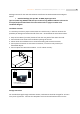
ROCPOWER – ROCFORCE ‐ Parallel Redundancy On‐Line ‐ user manual CHAPTER 7 Bundled Hardware and Software Installation Guide Hardware Installation Connect the male connector of RS232 cable to the UPS communication port. Connect the female connector of the RS232 cable to a dedicated RS232 port of the computer. Refer to Chapter 1 for installation of optional interface cards. Software Installation Please refer to the software User’s Manual for installation.
ROCPOWER – ROCFORCE ‐ Parallel Redundancy On‐Line ‐ user manual USE (USB) card CN1 is for USB. For communication protocol, please see the definition below: Comply with USB 1.0 and USB 1.5 Comply with USB HiD Version 1.0. The Pin Assignments of the USE card: 1 Æ VCC (+5V) 2 Æ D- 3 Æ D+ 4 Æ Ground Installation Position: slot 1 or slot 2. Use connector: A or B For installation, please refer to The Installation of the Interface Cards on page 37.
ROCPOWER – ROCFORCE ‐ Parallel Redundancy On‐Line ‐ user manual SNMP Cards SNMP/WEB card For installation, please refer to the card’s User Manual Installation Position: slot 1 or slot 2. Use connector: A or B For installation, please refer to Installation of the Interface Cards on this page. Net Agent II Internal Card For installation, please refer to the card’s User Manual Installation Position: slot 2. Use connector: C. For installation, please refer to Installation of the Interface Cards on this page.
ROCPOWER – ROCFORCE ‐ Parallel Redundancy On‐Line ‐ user manual 1 2 3 39
ROCPOWER – ROCFORCE ‐ Parallel Redundancy On‐Line ‐ user manual CHAPTER 8 Battery Replacement 1. Unscrew the battery panel as indicated in Step 1. 2. Remove the front panel as indicated in Step 2. 3. Remove the battery pack screw as shown in Step 3. 4. Unplug the battery connectors as shown in Step 4.
ROCPOWER – ROCFORCE ‐ Parallel Redundancy On‐Line ‐ user manual 5. Remove the battery packs from the battery bank as shown in Step 5. Recycling the Used Battery Contact your local recycling or hazardous waste center for information on the proper disposal of the used batteries.
ROCPOWER – ROCFORCE ‐ Parallel Redundancy On‐Line ‐ user manual CHAPTER 9 Specifications Model INPUT Voltage Window Frequency Phase/Wire Power Factor Current THD (100% linear load) OUTPUT Voltage Window Voltage Adjustment Voltage Regulation Capacity Rated Power Factor Wave Form Frequency Stability Frequency Regulation Transfer Time Crest Factor Efficiency(AC to AC, Normal) Efficiency(AC to AC, ECO) Autonomy DC Start BATTERY Type Quantity Voltage Recharge Time DISPLAY Status On LED + LCD Readings on LCD
ROCPOWER – ROCFORCE ‐ Parallel Redundancy On‐Line ‐ user manual System Fault Conditions PHYSICAL Tower model Dimensions (WxHxD )inch RT model 11.4x29.5x25.4 11.4x34.7x25.4 17.3x12.2x26.8 17.3x15.6x26.
ROCPOWER – ROCFORCE ‐ Parallel Redundancy On‐Line ‐ user manual CHAPTER 10 LIMITED WARRANTY This Limited Warranty is provided by Rocstorage, Inc. (hereinafter: Rocstor) for the Rocstor, Rocpower and Rocsecure lines of products. General Terms EXCEPT AS EXPRESSLY SET FORTH IN THIS LIMITED WARRANTY, ROCSTOR MAKES NO OTHER WARRANTIES OR CONDITIONS, EXPRESS OR IMPLIED, INCLUDING ANY IMPLIED WARRANTIES OF MERCHANTABILITY AND FITNESS FOR A PARTICULAR PURPOSE.
ROCPOWER – ROCFORCE ‐ Parallel Redundancy On‐Line ‐ user manual This Limited Warranty is provided by Rocstor for Rocpower lines of products used in the ordinary course of your business. Descriptions, Drawings and Specifications Rocstor products will substantially conform to the descriptions, drawings and specifications published by Rocstor. However, the descriptions, drawings and specifications are not warranties of performance and not warranties of fitness for a particular purpose.
ROCPOWER – ROCFORCE ‐ Parallel Redundancy On‐Line ‐ user manual Buyer’s Obligation under the Warranty The person requesting coverage under this warranty shall prove that he or she is the original purchaser and declares that the product has not been sold, leased, bartered or otherwise changed possession. The buyer must notify Rocstor and show proof of notification through any reasonable means of communication in which there is acknowledgment of receipt.
ROCPOWER – ROCFORCE ‐ Parallel Redundancy On‐Line ‐ user manual THIS LIMITED WARRANTY GIVES YOU SPECIFIC LEGAL RIGHTS. YOU MAY ALSO HAVE OTHER RIGHTS THAT MAY VARY FROM STATE TO STATE OR FROM COUNTRY TO COUNTRY. YOU ARE ADVISED TO CONSULT APPLICABLE STATE OR COUNTRY LAWS FOR A FULL DETERMINATION OF YOUR RIGHTS. Limitation on the Use of Any Rocstor “Rocpower” Product The product you purchased was not designed for direct or indirect patient care and treatment.
ROCPOWER – ROCFORCE ‐ Parallel Redundancy On‐Line ‐ user manual After the first ninety (90) days, technical support for software that was either preinstalled by Rocstor on the Rocstor branded product or included with the Rocstor branded product at the time of your purchase or lease of the product is available for a fee. WARNING The individual user should take care to determine prior to use whether this device is suitable, adequate or safe for the use intended.
ROCPOWER – ROCFORCE ‐ Parallel Redundancy On‐Line ‐ user manual Rocstor offers extra coverage for your product. For information on service upgrades, visit www.Rocstor.com. Service upgrades purchased in one country are not transferable to another country. Manual – Disclaimer Revisions to this manual occur periodically. Please go to the Rocstor website, www.rocstor.com to obtain the most current version of the User Manual.
ROCPOWER – ROCFORCE ‐ Parallel Redundancy On‐Line ‐ user manual Trademark Acknowledgements © 2008, Rocstorage, Inc; acknowledges the following trademarks for company names or products mentioned within the Rocstor site, portal pages and articles/text/manuals: Rocstor, Rocsecure and Rocpower are registered trademarks of Rocstorage, Inc. Rocwave, Rocforce, Smartroc, Rocsafe … are the trademarks of Rocstorage, Inc.
ROCPOWER – ROCFORCE ‐ Parallel Redundancy On‐Line ‐ user manual Contact Information Corporate Headquarters 8130 Remmet Avenue Canoga Park, CA 91304‐4129 Office: +1 (818) 449‐2000 Fax: +1 (818) 884‐8777 Email: info@Rocstor.com Technical Support / RMA Tel: (888) 877‐7716 (USA and Canada) Tel: +1 (818) 449‐2000 (Domestic and Internationals) Fax: +1 (818) 884‐8777 Hours: 9:00 am ‐ 5:00 pm PST Mon ‐ Fri (excluding holidays) Email: support@Rocstor.
ROCPOWER – ROCFORCE ‐ Parallel Redundancy On‐Line ‐ user manual www.ROCPOWER.