Rocsecure NE52 NAS System User’s Manual Revision 1.
NAS System Table of Contents Preface ..................................................................................................................................... 3 Before You Begin .................................................................................................................. 4 Safety Guidelines............................................................................................................................................................................
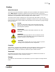
NAS System Preface About this manual This manual provides information regarding the quick installation and hardware features of the NAS system. Information contained in the manual has been reviewed for accuracy, but not for product warranty because of the various environment/OS/settings. Information and specifications will be changed without further notice.
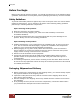
NAS System Before You Begin Before going through with this manual, you should read and focus to the following safety guidelines. Notes about the subsystem product packaging and delivery are also included.
NAS System Chapter 1 Introduction The NAS System 1.
NAS System 1.2 Technical Specifications Hardware Platform Intel Celeron Quad Core 2.0GHz CPU Cache memory : 8GB DDR3 SDRAM One USB3.0, one eSATA and two USB2.0 ports Two Gigabit Ethernet ports Up to Five(5) 2.5"/3.5” hot-swappable 6Gb/s SATA hard drives Real-time drive activity and status indicators Environmental monitoring unit 300W power supply with PFC (80 plus) Support drive hot spare and automatic hot rebuild Locally audible event notification alarm Power requirements AC 100V ~ 240V Full range 6.
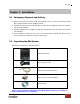
NAS System Chapter 2 Installation 2.1 Packaging, Shipment and Delivery Before removing the system from the shipping carton, you should visually inspect the physical condition of the shipping carton. Unpack the system and verify that the contents of the shipping carton are all there and in good condition. Exterior damage to the shipping carton may indicate that the contents of the carton are damaged.
NAS System 2.3 Identifying Parts of the NAS System The illustrations below identify the various parts of the NAS system. 2.3.
NAS System 2.3.2 HDD Status LEDs Green LED indicates power is on and the hard disk drive status is good for this slot. Blinking Orange and Green LED indicates the hard disk drive is in rebuilding state. 2.3.3 Fan Fail LED Parts Function Fan Fail LED When fan fails, this LED will turn red and an alarm will sound. 2.3.4 Lock Indicator Every Drive Carrier is lockable and is fitted with a lock indicator to indicate whether or not the carrier is locked into the chassis.
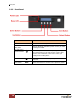
NAS System 2.3.5 Front Panel PARTS Power LED Green LED indicates power is on. Busy LED Orange blinking indicates system is busy or data is being accessed. Up and Down Arrow buttons Use the Up or Down arrow keys to go through the information on the LCD screen. This is also used to move between each menu when you configure the subsystem. This is used to enter the option you have selected. Select button Exit button 10 FUNCTION User’s Manual EXIT Press this button to return to the previous menu.
NAS System 2.3.6 Rear View 1. Power On/Off Switch – Use this switch to power on the NAS System. 2. AC Power Input Socket - Use this to connect the power cords connected from power source. 3. Serial Port - Connects to serial-based mouse or data processing devices. 4. Video Port - The video in port allows connect to video in, which can also apply to video loop thru function. 5. HDMI Port - Two HDMI port is located at the rear of the system.
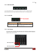
NAS System 2.3.7 LCD Menu Diagram MODEL xxx.xxx.xxx.xxx VERSION 3.x.xx CHANGE PASSWORD NEW PASSWORD 00000000 SUBMIT PASSWORD SETTING(YES/NO) BEEPER SETTING SETTING MUTE / ALARM SUBMIT BEEPER SETTING(YES/NO) CPU NORMAL FAN NORMAL DISK NORMAL POWER NORMAL TEMP NORMAL RAID NORMAL DISK INFORMATION DISK_1 *O* TEMP 35C : DISK_05 *O* TEMP 35C RAID INFORMATION ARRAY NAME RAID LEVEL NETWORK INFORMATION ETHO IP xxx.xxx.xxx.xxx ETH1 IP xxx.xxx.xxx.
NAS System 2.4 Getting Started with the NAS System 2.4.1 NAS Hardware Setup 1. Attach network cable to LAN0 Ethernet port. Connect the other end of network cable to your network hub or switch. You may also connect the other Ethernet ports if needed. 2. Plug in the power cord into the AC Power Input Socket located at the rear of the subsystem. 3. To turn on the NAS, press the Power On/Off Switch of power supply at the rear. Then turn on the main switch button in the front panel. 4.
NAS System b. Place the hard drive in the disk tray. c. Make sure the holes of the disk tray align with the holes of the hard drive. Install the mounting screws on the bottom part to secure the drive in the disk tray. Tray Hole A d. Slide the tray into a slot and push the Lock Indicator Button. e. Press the handle until you hear the latch click into place. The HDD status LED will turn green if subsystem is on.
NAS System 2.4.2.2 Installing 2.5” Disk in a Disk Tray a. Make sure the lock indicator is in unlocked position. To pull out a disk tray, press the carrier open button. Drive Tray is Unlocked b. Pull out an empty disk tray. Pull the lever handle outwards to remove the carrier from the enclosure. c. Place the 2.5” hard drive in the disk tray.
NAS System d. Install the mounting screws on the bottom part to secure the drive in the disk tray. Tray Hole W e. Slide the tray into a slot. f. 16 Close the lever handle until you hear the latch click into place.