
User manual


www.rogerblackfitness.co.uk
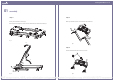
parts list
01 assembly
PART DESCRIPTION QTY.
53 8mm Washer 6
59 M8 x 43mm Bolt 4
68 M8 x 18mm Bolt 2
A Safety Key 1
B Power Cord 1
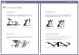
pre-assembly notes
OPEN THE BOXES
Make sure to inventory all of the parts that are included in the boxes. Check the Hardware Chart for a
full count of the number of parts included for proper assembly. If you are missing any parts please call
the Roger Black Technical Support line on 0845 600 0464.
GATHER YOUR TOOLS
Before starting the assembly of your unit, gather the necessary tools. Having all of the equipment at
hand will save time and make the assembly quick and hassle-free.
CLEAR YOUR WORK AREA
Make sure that you have cleared away a large enough space to properly assemble the unit. Make sure
the space is free from anything that may cause injury during assembly. After the unit is fully assembled,
make sure there is a comfortable amount of free area around the unit for unobstructed operation.
INVITE A FRIEND
Some of the assembly steps may require heavy lifting. It is recommended that you obtain the assistance
of another person when assembling this product.
hardware chart
For your convenience, we have identified the hardware used in the assembly of this product. This chart
is provided to help you identify those items that may be unfamiliar to you.
NO. DESCRIPTION QTY.
1 Running Belt 1
2 Motor Shroud 1
3 Right Rear End Cap 1
4 Left Rear End Cap 1
5 Extruded Rail, Right 1
6 Extruded Rail, Left 1
7 Front Roller 1
8 Front Roller Shaft 1
9 Rear Roller 1
10 Rear Roller Shaft 1
11 Wooden Deck 1
12 Drive Belt 1
13 Main Frame 1
14 Front Shroud 1
15 Control Board 1
16 Motor Bracket 1
17 Motor 1
18 Motor Bottom Cover 1
19 Handlebar Grip 2
20 Handlebar 1
21 Computer 1
22 Hand Pulse Sensor 2
23 Console Top 1
24 Console Button 1
25 Upright, Right 1
26 Upright, Left 1
27 Base Frame 1
28 Rear End Caps 2sets
29 Fan 1
30 Safety Key 1
32 Caster Holder 2
33 Rear Wheel 2
34 Base Frame End Cap 2
35 Handlebar End Cap 2
36 Support 1
37 Rear End Cap Screw 4
38 Rear Roller Bolt 2
39 Roller Washer 3
40 Rubber Cushion Bolt 6
41 Rail Guide 6
NO. DESCRIPTION QTY.
42 Rail Guide Screw 12
43 Motor Adjustment Bolt 1
44 8 x 23mm Washer 2
45 Motor Bumper Bushing 1
46 M8 Nylon Nut 2
47 8 x 16mm Washer 2
48 M8 x 12mm Socket Bolt 2
49 M10 x 116mm Bolt 1
50 10 x 23mm Washer 1
51 M10 Nut 1
52 M8 x 45mm Bolt 2
53 8mm Washer 16
54
55 Front Roller Bolt 1
56 M8 Nut 2
57 4 x 14mm Screw 4
58 Base Frame Cushion 4
59 M8 x 43mm Bolt 9
60 Spring 1
61 Plastic Washer 2
62 M12 x 80mm Bolt 2
63 M8 x 32mm Bolt 1
64 Plastic Wheel 1
65 4 x 25mm Screw 2
66 4 x 12mm Screw 15
67 Motor Bottom Tray 1
68 M8 x 18mm Bolt 2
69 Power Switch Board 1
70 20 x 40mm Washer N/A
71 M16 x 54mm Bolt N/A
72 Bumper N/A
73 U Bracket N/A
74 M10 x 67mm Bolt N/A
75 Base Motor N/A
76 28 x 8 x 3mm Washer 2
77 10mm Washer 1
78 Spring N/A
79 Elevation Support N/A
80 Foot Up Lock N/A
81 Water Bottle Holder 2
82 Lock Pin 1
53 68 59
A
B
Fig. 2: Hardware
12
4 x 1
4 mm Scre
w
PDF compression, OCR, web optimization using a watermarked evaluation copy of CVISION PDFCompressor