TABLE OF CONTENTS 1) Introduction 2 2) Unpacking the Cronus integrated amplifier 2 3) Installing the Cronus into your system 3 4) Operation of the Cronus 5 5) Setting the tube bias 5 6) Troubleshooting 7 7) Registration card 7 8) Fuse values 8 9) Specifications 8 10) Warranty 9 1
INTRODUCTION Congratulations on your purchase decision! We at Rogue Audio truly believe that our amplifiers provide the “smartest” value in high-end audio. If you have never owned a vacuum tube amplifier you will be thrilled by the silky-smooth sound and incredible detail that only a tube amplifier can provide. And with the Cronus integrated amplifier, you can be sure that you are getting the very best in tube amplification.
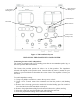
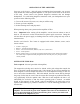
Right Channel Binding Post Left Channel Binding Post Potentiometers Bias Meter Bias Switches 12AU7 Center (Preamp Tube) Figure 1. Tube and Deck Layout INSTALLING THE CRONUS INTO YOUR SYSTEM Connecting Cronus to the Loudspeakers: The Cronus is equipped with 5 way binding posts that can accommodate spade, lug, or bare wire speaker cable terminations. The Cronus also provides options for either 4 or 8 ohm speakers. The impedance selected will depend on the speakers used.
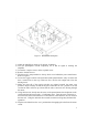
Connecting Cronus to source components: The input connections to the Cronus are made via RCA jacks on the rear of the amplifier. See figure 2. Be sure to use high quality interconnect cables – they do make a difference Main Fuse Right Channel Binding Post Left Channel Binding Post RCA Inputs Variable and Fixed Outputs Figure 1. Rear panel layout Connecting Cronus to a turntable: The phono section provided in the Cronus is suitable for a wide variety of cartridges.
OPERATION OF THE AMPLIFIER Powering up the System - After all proper connections have been made, you are now ready to turn the Cronus integrated amplifier on. The power on/off switch is on the front of the amp. Some sources can generate dangerous transients that can damage loudspeakers. To avoid letting dangerous transients reach your loudspeakers turn your system on in the following order: 1) Turn on all sources (CD, tuner, etc.) that you will be using.
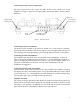
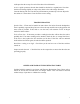
Figure 3. Removable hatch plate 1) Allow the amplifier to warm up for at least 30 minutes. 2) Turn the preamplifier volume completely off so that no signal is entering the amplifier 3) Loosen the 2 captive screws on the top hatch cover. 4) Remove the hatch cover. 5) The bias tool is snap attached to the top deck cover behind the power transformer. Refer to Figure 1. 6) Locate the toggle switches and associated small potentiometers (they are blue and have a small screw in the top).
10) Repeat the above steps for each of the tubes in both channels. As it is a quick operation, the tube bias should be checked on a regular basis. Note that the bias will change slightly on a day to day basis as the wall voltage fluctuates. Constant biasing will wear out the bias potentiometers prematurely so do not adjust the bias unless it is more than 4-5 mA from the correct setting.
FUSE VALUES Main fuse located on rear panel (1) – 5 Amp slow blow Tube Fuses (4) – 1/4 Amp slow blow Power Supply Fuse on PCB (1) – ¾ Amp slow blow SPECIFICATIONS output power 55 WPC frequency response 5Hz – 50 kHz ± 1dB THD < 0.1% typ, < 1% at rated power input sensitivity 1.
LIMITED WARRANTY Warranty Period This product has been manufactured under the highest standards of quality and workmanship. Rogue Audio Inc. (hereinafter “Rogue Audio”) warrants this product against defects in material or workmanship as follows: With the exception of vacuum tubes, Rogue Audio warrants to the original purchaser of this product all parts of this product against defects in material and workmanship for a period of three years from the date of retail purchase.