® R&S Scope Rider RTH Digitales HandheldOszilloskop Erste Schritte (=J?Ë3) Erste Schritte Messtechnik 1326.1561.
In diesem Handbuch werden folgende R&S®RTH-Modelle beschrieben: ● R&S®RTH1002 (1317.5000.K02) ● R&S®RTH1004 (1317.5000.K04) Dieses Handbuch steht in verschiedenen Sprachen auf der R&S RTH-Produktseite unter www.rohde-schwarz.com/product/rth.html > "Downloads > Manuals" zum Download bereit. Die in diesem Produkt enthaltene Software verwendet mehrere wichtige Open-Source-Softwarepakete. Informationen finden Sie im Dokument "Open Source Acknowledgement", das auf der R&S RTH-Produktseite unter http://www.
Grundlegende Sicherheitshinweise Lesen und beachten Sie unbedingt die nachfolgenden Anweisungen und Sicherheitshinweise! Alle Werke und Standorte der Rohde & Schwarz Firmengruppe sind ständig bemüht, den Sicherheitsstandard unserer Produkte auf dem aktuellsten Stand zu halten und unseren Kunden ein höchstmögliches Maß an Sicherheit zu bieten. Unsere Produkte und die dafür erforderlichen Zusatzgeräte werden entsprechend der jeweils gültigen Sicherheitsvorschriften gebaut und geprüft.
Grundlegende Sicherheitshinweise Die Einhaltung der Sicherheitshinweise dient dazu, Verletzungen oder Schäden durch Gefahren aller Art auszuschließen. Hierzu ist es erforderlich, dass die nachstehenden Sicherheitshinweise vor der Benutzung des Produkts sorgfältig gelesen und verstanden sowie bei der Benutzung des Produkts beachtet werden. Sämtliche weitere Sicherheitshinweise wie z.B. zum Personenschutz, die an entsprechender Stelle der Produktdokumentation stehen, sind ebenfalls unbedingt zu beachten.
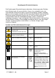
Grundlegende Sicherheitshinweise Symbol Bedeutung Achtung beim Umgang mit elektrostatisch gefährdeten Bauelementen Symbol Bedeutung EU - Kennzeichnung für die getrennte Sammlung von Elektround Elektronikgeräten. Elektroaltgeräte dürfen nicht über unsortierten Siedlungsabfall entsorgt werden, sondern müssen getrennt gesammelt werden. Weitere Informationen siehe Seite 11. Warnung vor Laserstrahl Produkte mit Laser sind je nach ihrer Laser-Klasse mit genormten Warnhinweisen versehen.
Grundlegende Sicherheitshinweise Signalworte und ihre Bedeutung Die folgenden Signalworte werden in der Produktdokumentation verwendet, um vor Risiken und Gefahren zu warnen. kennzeichnet eine unmittelbare Gefährdung mit hohem Risiko, die Tod oder schwere Körperverletzung zur Folge haben wird, wenn sie nicht vermieden wird. kennzeichnet eine mögliche Gefährdung mit mittlerem Risiko, die Tod oder (schwere) Körperverletzung zur Folge haben kann, wenn sie nicht vermieden wird.
Grundlegende Sicherheitshinweise 2. Stellen Sie das Produkt nicht auf Oberflächen, Fahrzeuge, Ablagen oder Tische, die aus Gewichts- oder Stabilitätsgründen nicht dafür geeignet sind. Folgen Sie bei Aufbau und Befestigung des Produkts an Gegenständen oder Strukturen (z.B. Wände und Regale) immer den Installationshinweisen des Herstellers. Bei Installation abweichend von der Produktdokumentation können Personen verletzt, unter Umständen sogar getötet werden. 3.
Grundlegende Sicherheitshinweise 4. Sofern das Produkt nicht mit einem Netzschalter zur Netztrennung ausgerüstet ist, beziehungsweise der vorhandene Netzschalter zu Netztrennung nicht geeignet ist, so ist der Stecker des Anschlusskabels als Trennvorrichtung anzusehen. Die Trennvorrichtung muss jederzeit leicht erreichbar und gut zugänglich sein. Ist z.B. der Netzstecker die Trennvorrichtung, darf die Länge des Anschlusskabels 3 m nicht überschreiten.
Grundlegende Sicherheitshinweise 12. Wird ein Produkt ortsfest angeschlossen, ist die Verbindung zwischen dem Schutzleiteranschluss vor Ort und dem Geräteschutzleiter vor jeglicher anderer Verbindung herzustellen. Aufstellung und Anschluss darf nur durch eine Elektrofachkraft erfolgen. 13.
Grundlegende Sicherheitshinweise 2. Bevor Sie das Produkt bewegen oder transportieren, lesen und beachten Sie den Abschnitt "Transport". 3. Wie bei allen industriell gefertigten Gütern kann die Verwendung von Stoffen, die Allergien hervorrufen - so genannte Allergene (z.B. Nickel) - nicht generell ausgeschlossen werden. Sollten beim Umgang mit R&S-Produkten allergische Reaktionen, z.B.
Grundlegende Sicherheitshinweise Gerät der Klasse B: Ein Gerät, das sich für den Betrieb im Wohnbereich sowie in solchen Bereichen eignet, die direkt an ein Niederspannungs-Versorgungsnetz angeschlossen sind, das Wohngebäude versorgt. Reparatur und Service 1. Das Produkt darf nur von dafür autorisiertem Fachpersonal geöffnet werden. Vor Arbeiten am Produkt oder Öffnen des Produkts ist dieses von der Versorgungsspannung zu trennen, sonst besteht das Risiko eines elektrischen Schlages. 2.
Grundlegende Sicherheitshinweise 5. Bei Undichtheit einer Zelle darf die Flüssigkeit nicht mit der Haut in Berührung kommen oder in die Augen gelangen. Falls es zu einer Berührung gekommen ist, den betroffenen Bereich mit reichlich Wasser waschen und ärztliche Hilfe in Anspruch nehmen. 6. Werden Zellen oder Batterien, die alkalische Elektrolyte enthalten (z.B. Lithiumzellen), unsachgemäß ausgewechselt oder geladen, besteht Explosionsgefahr.
Grundlegende Sicherheitshinweise Entsorgung 1. Batterien bzw. Akkumulatoren, die nicht mit dem Hausmüll entsorgt werden dürfen, darf nach Ende der Lebensdauer nur über eine geeignete Sammelstelle oder eine Rohde & Schwarz-Kundendienststelle entsorgt werden. 2. Am Ende der Lebensdauer des Produktes darf dieses Produkt nicht über den normalen Hausmüll entsorgt werden, sondern muss getrennt gesammelt werden. Rohde & Schwarz GmbH & Co.
Sicherheitshinweise für wiederaufladbare Li-Ion-Batterien Mögliche schwere Verletzungen, unter Umständen mit Todesfolge. Beachten Sie die folgenden Hinweise vollständig, um schwere Verletzungen von Personen - unter Umständen mit Todesfolge durch Explosion und/oder Brand zu verhindern. 1. Batterien nicht zerlegen, öffnen, zerkleinern oder aus großer Höhe fallen lassen. Bei mechanischer Beschädigung besteht die Gefahr des Austritts von Chemikalien. Austretende Gase können zu Atembeschwerden führen.
Customer Support Technischer Support – wo und wann Sie ihn brauchen Unser Customer Support Center bietet Ihnen schnelle, fachmännische Hilfe für die gesamte Produktpalette von Rohde & Schwarz an. Ein Team von hochqualifizierten Ingenieuren unterstützt Sie telefonisch und arbeitet mit Ihnen eine Lösung für Ihre Anfrage aus - egal, um welchen Aspekt der Bedienung, Programmierung oder Anwendung eines Rohde & Schwarz Produktes es sich handelt.
R&S®Scope Rider RTH Inhalt Inhalt 1 Einführung..............................................................................5 1.1 Hauptmerkmale..................................................................................... 5 1.2 Eingangsisolierung...............................................................................5 1.3 Messkategorien.....................................................................................6 1.4 Überblick über die Dokumentation...................................
R&S®Scope Rider RTH Inhalt 4.3.3 Tasten an der Frontplatte verwenden................................................... 32 4.4 Unbekanntes Signal anzeigen........................................................... 34 4.5 Modus auswählen............................................................................... 35 4.6 Datum, Uhrzeit und Sprache einstellen............................................ 36 4.7 Informationen und Hilfe aufrufen...................................................... 37 4.7.
R&S®Scope Rider RTH Einführung Eingangsisolierung 1 Einführung 1.1 Hauptmerkmale Das R&S RTH ist das perfekte Mehrzweckwerkzeug für das Labor und im Feld. Es zeichnet sich durch folgende Hauptmerkmale aus: ● Vollständige Isolierung aller Kanäle und Schnittstellen ● Sicherheitseinstufung CAT IV 600 V / CAT III 1000 V ● Bandbreite von 60 MHz bis 500 MHz mit Abtastrate von 5 GS/s ● Erfassungsgeschwindigkeit von bis zu 50.
R&S®Scope Rider RTH Einführung Messkategorien Bild 1-1: Isolierungsschema des R&S RTH Die Eingangsisolierung hat mehrere Vorteile: ● Unabhängig potenzialfreie Signale können simultan gemessen werden. ● Das Risiko, bei der Messung mehrerer Signale einen Kurzschluss zu verursachen, ist deutlich reduziert. ● Bei der Messung von Signalen mit unterschiedlichen Massen werden die induzierten Erdströme auf einem Minimum gehalten. 1.
R&S®Scope Rider RTH Einführung Messkategorien Für Messungen von Stromkreisen, die nicht direkt an das Netz angeschlossen sind, z. B. Elektrogeräte, batteriegespeiste Stromkreise und besonders geschützte Sekundärkreise. Diese Messkategorie ist auch als CAT I bekannt. ● CAT II: Für Messungen von Stromkreisen, die über eine Standardsteckdose direkt an die Niederspannungsanlage angeschlossen sind, z. B. Haushaltsgeräte und tragbare Elektrowerkzeuge.
R&S®Scope Rider RTH Einführung Überblick über die Dokumentation 1.4 Überblick über die Dokumentation Die Benutzerdokumentation für den R&S RTH besteht aus folgenden Teilen: ● Gerätehilfe (Instrument Help) Die Gerätehilfe ist Teil der Firmware des Geräts. Sie ermöglicht einen schnellen, kontextbezogenen Zugriff auf alle Informationen direkt auf dem Gerät.
R&S®Scope Rider RTH Einführung Regularien wendet wird. Es ist auf der R&S RTH-Website unter www.rohde-schwarz.com/ product/rth.html > „Downloads“ > „Firmware“ verfügbar und kann direkt auf dem Gerät gelesen werden. 1.5 Regularien Teil 15 der FFC- und RSS-210 der IC-Bestimmungen Dieses Gerät entspricht Teil 15 der FCC-Bestimmungen und dem RSS-Standard der Industry Canada-(IC-)Bestimmungen.
R&S®Scope Rider RTH 2 Inbetriebnahme Inbetriebnahme In diesem Abschnitt werden die grundlegenden Schritte zur ersten Inbetriebnahme des R&S RTH beschrieben. Stromschlaggefahr durch Hochspannungen Betreiben Sie das Gerät immer ordnungsgemäß, um elektrischen Schlag, Brand, Verletzungen von Personen oder sonstige Schäden zu verhindern. ● Öffnen Sie das Gerätegehäuse nicht. ● Verwenden Sie das Gerät nicht, wenn das Gerätegehäuse, das Display oder ein Tastkopf oder Zubehörteil beschädigt ist.
R&S®Scope Rider RTH Inbetriebnahme Gerät auspacken Stromschlaggefahr durch Hochspannungen ● Halten Sie die im Datenblatt angegebenen Betriebsbedingungen ein. Beachten Sie, dass die allgemeinen Sicherheitshinweise auch Informationen zu Betriebsbedingungen enthalten, die eine Beschädigung des Geräts vermeiden. ● Lesen und beachten Sie die Broschüre „Grundlegende Sicherheitshinweise“ (Basic Safety Instructions), die in gedruckter Form mit dem Gerät geliefert wird.
R&S®Scope Rider RTH Inbetriebnahme Batterie einsetzen und laden Paketinhalt Das Lieferpaket enthält folgende Teile: ● R&S RTH Handheld-Oszilloskop ● 4 GByte microSD-Karte, eingesetzt in das Batteriefach ● Netzteil mit Kabel und Adapterset für verschiedene Steckdosentypen ● Batterie-Pack ● Tastkopf R&S RT-ZI10 (2x für R&S RTH1002; 4x für R&S RTH1004) ● DMM-Testkabel (nur für R&S RTH1002) ● Handschlaufe, befestigt am Handheld-Oszilloskop ● Handbuch "Erste Schritte" und Broschüre "Grundlegende Sicherheitshin
R&S®Scope Rider RTH Inbetriebnahme Batterie einsetzen und laden 1. Klappen Sie den Kippständer an der Rückseite des Geräts aus. 2. Schrauben Sie die Batterieabdeckung auf. 3. Setzen Sie das Batterie-Pack ein. 4. Schrauben Sie die Batterieabdeckung fest. 5. Verbinden Sie das Netzteil mit dem Anschluss an der linken Seite des Oszilloskops und laden Sie die Batterie vollständig auf. Der Ladevorgang kann einige Stunden dauern. Erste Schritte 1326.1561.
R&S®Scope Rider RTH Inbetriebnahme Kippständer verwenden Ist das Gerät eingeschaltet, wird der Batteriezustand am Display angezeigt. Ersetzen Sie gebrauchte Batterien nach einer Nutzungsdauer von 24 Monaten durch neue Batterien. Beachten Sie die Sicherheitsbestimmungen im Kapitel "Batterien und Akkumulatoren/Zellen" in der Broschüre "Grundlegende Sicherheitshinweise" (Basic Safety Instructions), die mit dem Gerät geliefert wird. 2.
R&S®Scope Rider RTH Inbetriebnahme EMV-Schutzmaßnahmen ► Klappen Sie den Kippständer wie unten gezeigt aus. 2.5 EMV-Schutzmaßnahmen Elektomagnetische Störung kann zur Verfälschung von Messergebnissen führen. Um die elektromagnetische Störstrahlung während des Betriebs gering zu halten, müssen die folgenden Voraussetzungen erfüllt sein: ● Verwenden Sie nur geeignete, geschirmte Kabel hoher Qualität, zum Beispiel doppelgeschirmte HF- und LAN-Kabel. ● Schließen Sie alle offenen Kabelenden ab.
R&S®Scope Rider RTH Geräteübersicht Frontansicht 3 Geräteübersicht 3.1 Frontansicht Bild 3-1: Frontplatte des R&S RTH1002 1 = Touchscreen 2 = Messkurvenaufbau mit AUTOSET, Rücksetzen auf Grundeinstellung mit PRESET 3 = Analysefunktionen 4 = Modus-Auswahl 5 = Speichern/Abrufen 6 = Geräteeinstellungen 7 = Ein-/Ausschalten 8 = Navigationselemente 9 = Horizontale Einstellungen 10 = Erfassung starten/stoppen und Triggereinstellungen Erste Schritte 1326.1561.
R&S®Scope Rider RTH Geräteübersicht Frontansicht 11 = Erfassungseinstellungen 12 = Screenshot und Dokumentationsausgabe 13 = Kanäle und vertikale Einstellungen 14 = Multimeter-Messungen Bild 3-2: Frontplatte des R&S RTH1004 1 = Touchscreen 2 = Messkurvenaufbau mit AUTOSET, Rücksetzen auf Grundeinstellung mit PRESET 3 = Analysefunktionen 4 = Modus-Auswahl 5 = Speichern/Abrufen 6 = Geräteeinstellungen 7 = Ein-/Ausschalten 8 = Navigationselemente 9 = Horizontale Einstellungen 10 = Erfassung starten/stoppen
R&S®Scope Rider RTH Geräteübersicht Oberseite Eine Beschreibung der Tasten finden Sie in Kapitel 4.3.3, "Tasten an der Frontplatte verwenden", auf Seite 32. 3.2 Oberseite Das R&S RTH1002 besitzt zwei BNC-Eingänge (CH1, CH2) und zwei 4-mmBananensteckbuchsen für verschiedene Multimeter-Messungen. Die Kanaleingänge verfügen über doppelte Kanal-zu-Kanal-Isolierung, die unabhängige potenzialfreie Messungen an jedem Eingang ermöglicht.
R&S®Scope Rider RTH Geräteübersicht Oberseite Stromschlaggefahr durch Hochspannungen Beachten Sie Folgendes, um Stromschläge und Personenschäden zu vermeiden und eine Beschädigung des Geräts oder anderer Produkte, die daran angeschlossen sind, zu verhindern: ● Legen Sie keine Eingangsspannungen an, die den Nennwert des Geräts und des Zubehörs überschreiten. ● Verwenden Sie nur Tastköpfe, Testkabel und Adapter, die der Messkategorie (CAT) Ihrer Messaufgabe entsprechen.
R&S®Scope Rider RTH Geräteübersicht Rechte Seite 3.3 Rechte Seite 1 = LAN 2 = USB Typ B für Fernsteuerung 3 = Tastkopfkompensation 4 = USB Typ A für Flash-Laufwerk 5 = Anschluss für logischen Tastkopf Gefahr von Verletzungen oder Schäden am Gerät Schließen Sie immer die Abdeckungen der Kommunikationsanschlüsse und des DC-Eingangs, wenn sie nicht belegt sind. LAN-Anschluss RJ-45-Anschluss für die Anbindung des Geräts an ein LAN (Local Area Network). Unterstützt bis zu 100 MBit/s.
R&S®Scope Rider RTH Geräteübersicht Linke Seite Anschluss für logischen Tastkopf Eingang für den logischen Tastkopf R&S RT-ZL04. Für Logikanalysen ist die Mixed-Signal-Option R&S RTH-B1 erforderlich, die den logischen Tastkopf R&S RT-ZL04 einschließt. Gefahr eines Stromschlags - keine CAT-Einstufung für MSO-Messungen Der logische Tastkopf R&S RT-ZL04 ist in keine Messkategorie eingestuft.
R&S®Scope Rider RTH Geräteübersicht Display im Überblick 3.5 Display im Überblick In den wichtigsten Betriebsarten (Oszilloskop, Maske und XY) zeigt das Display die folgenden Informationen an.
R&S®Scope Rider RTH Geräteübersicht Display im Überblick verschieben. Alternativ können Sie auf den Marker tippen, um den Fokus darauf zu setzen, und mit dem Drehrad die Position anpassen. Erste Schritte 1326.1561.
R&S®Scope Rider RTH Bedienung des Geräts Tastköpfe anschließen 4 Bedienung des Geräts 4.1 Tastköpfe anschließen Stromschlaggefahr durch Hochspannungen Stellen Sie sicher, dass das Teilerverhältnis auf dem Gerät auf den verwendeten Tastkopf eingestellt wird. Andernfalls geben die Messergebnisse nicht den tatsächlichen Spannungspegel wieder und Sie schätzen das tatsächliche Risiko möglicherweise falsch ein. 1.
R&S®Scope Rider RTH Bedienung des Geräts Funktionen aufrufen Hinweis: Bei Strommessungen mit einem Nebenschlusswiderstand als Strommesskopf müssen Sie den V/A-Wert des Widerstands mit der Dämpfung des Tastkopfs multiplizieren. Werden beispielsweise ein 1 Ω-Widerstand und ein 10:1-Tastkopf verwendet, ist der V/A-Wert des Widerstands 1 V/A, hat der Tastkopf den Teilerfaktor 0,1 und ergibt sich eine Stromtastkopfdämpfung von 100 mV/A. 4.
R&S®Scope Rider RTH Bedienung des Geräts Funktionen aufrufen 4.3.1 Touchscreen verwenden Die Verwendung des Touchscreens des R&S RTH ist so einfach wie bei einem Handy. Tippen Sie zum Öffnen des Menüs auf die „Menütaste“ - das ist das R&SLogo in der rechten unteren Ecke des Displays. Bild 4-2: Menü öffnen und einen Menüpunkt auswählen Erste Schritte 1326.1561.
R&S®Scope Rider RTH Bedienung des Geräts Funktionen aufrufen Bild 4-3: Ein- oder ausschalten (links) und einen Parameterwert auswählen (rechts) Bild 4-4: Numerischen Wert und die Einheit eingeben Erste Schritte 1326.1561.
R&S®Scope Rider RTH Bedienung des Geräts Funktionen aufrufen 4.3.2 Navigationsrad verwenden Zusätzlich oder alternativ zum Touchscreen können Sie das R&S RTH mit dem Drehrad bedienen. Achten Sie bei Verwendung des Drehrads immer darauf, auf welcher Position der Fokus liegt - das ist der orange Rahmen oder eine andere Hervorhebung, die das aktive Objekt in der Anzeige markiert. ● Fokus liegt auf der Menütaste oder irgendwo im Menü oder in den Dialogen: – Drehen Sie das Rad, um den Fokus zu verschieben.
R&S®Scope Rider RTH Bedienung des Geräts Funktionen aufrufen Bild 4-5: Menü öffnen und einen Menüpunkt auswählen Numerischen Wert über das Drehrad einstellen 1. Setzen Sie den Fokus auf die gewünschte Einstellung und drücken Sie einmal die Drehradtaste. 2. Drehen Sie das Rad, bis der gewünschte Wert angezeigt wird. 3. Drücken Sie BACK. Erste Schritte 1326.1561.
R&S®Scope Rider RTH Bedienung des Geräts Funktionen aufrufen Bild 4-6: Numerischen Wert über das Drehrad einstellen Dateneingabe über Drehrad und Tastenfeld Sie können genaue numerische Werte über das Tastenfeld eingeben. Siehe auch Bild 4-7. 1. Setzen Sie den Fokus auf die gewünschte Einstellung und drücken Sie zweimal die Drehradtaste. 2. Drehen Sie das Rad, bis der Fokus auf der gewünschten Ziffer liegt. 3. Drücken Sie die Drehradtaste. 4.
R&S®Scope Rider RTH Bedienung des Geräts Funktionen aufrufen Bild 4-7: Numerischen Wert und die Einheit über das Tastenfeld eingeben Erste Schritte 1326.1561.
R&S®Scope Rider RTH Bedienung des Geräts Funktionen aufrufen Mit dem Button SHIFT wird der Drehradfokus im Tastenfeld umgeschaltet. Liegt der Fokus auf dem Eingabefeld, ändert sich beim Drehen des Rads der Wert. Liegt der Fokus im unteren Teil, werden mit dem Drehrad Zahlen und Einheit ausgewählt. 4.3.3 Tasten an der Frontplatte verwenden Einen Überblick über die Tasten an der Frontplatte gibt Bild 3-2.
R&S®Scope Rider RTH Bedienung des Geräts Funktionen aufrufen Taste Kurz drücken Lange drücken Erfordert die Logikanalyseoption R&S RTH- Öffnet oder schließt den Dialog „Logik“ (Logic) zur KonfiB1 (MSO). Die Wirkung hängt vom Zustand der digitalen guration digitaler Kanäle. Kanäle ab: Sind alle digitalen Kanäle inaktiv, wird D0..D7 mit der Taste eingeschaltet und der Fokus darauf gesetzt. Sind die digitalen Kanäle aktiv, aber nicht im Fokus, wird mit der Taste der Fokus darauf gesetzt.
R&S®Scope Rider RTH Bedienung des Geräts Unbekanntes Signal anzeigen Taste Kurz drücken Lange drücken Nur R&S RTH1002: DMM startet oder stoppt die Multimeter-Messungen (entspricht MODE = „Multimeter“ (Meter)). DMM REL aktiviert oder deaktiviert relative Multimeter-Messungen. Öffnet oder schließt den Dialog „Multimeter“ (Meter) zur Konfiguration der Messungen. TIME und POS stellen die horizontale Zeitskala und Position des Triggerpunkts ein.
R&S®Scope Rider RTH Bedienung des Geräts Modus auswählen talen, vertikalen und Triggereinstellungen für das Anzeigen stabiler Messkurven an. 1. Drücken Sie die Taste PRESET. PRESET setzt das Gerät auf die werksseitigen Grundeinstellungen zurück. Die vorherige benutzerdefinierte Konfiguration wird entfernt und alle Kanäle außer Kanal 1 werden deaktiviert. 2. Drücken Sie die Taste AUTOSET. Die Messkurve wird angezeigt. 4.
R&S®Scope Rider RTH Bedienung des Geräts Datum, Uhrzeit und Sprache einstellen 4.6 Datum, Uhrzeit und Sprache einstellen Das Gerät besitzt eine Uhr für Datum und Uhrzeit. Sie können die Uhr auf die Lokalzeit einstellen und die Anzeigesprache auswählen. Unterstützte Sprachen sind im Datenblatt aufgelistet. Die Hilfe steht in Englisch zur Verfügung. Ein Neustart des Geräts ist nicht erforderlich. Datum und Uhrzeit einstellen Erste Schritte 1326.1561.
R&S®Scope Rider RTH Bedienung des Geräts Informationen und Hilfe aufrufen Anzeigesprache einstellen 4.7 Informationen und Hilfe aufrufen In den meisten Dialogen erklären Grafiken die Bedeutung der ausgewählten Einstellung. Wenn Sie weitere Informationen benötigen, können Sie die Hilfe öffnen, die Funktionsbeschreibungen der Einstellungen mit Links zu den entsprechenden Fernsteuerbefehlen sowie Hintergrundinformationen enthält. 4.7.
R&S®Scope Rider RTH Bedienung des Geräts Informationen und Hilfe aufrufen Wenn ein Dialog geöffnet ist, wird das Hilfethema des Dialogs neben dem Dialog angezeigt. Wenn ein Menü geöffnet ist, wird das Inhaltsverzeichnis angezeigt. Informationen zu einer Einstellung anzeigen Wenn ein Dialog und das Hilfefenster geöffnet sind, lassen sich die Informationen zu jeder Einstellung des Dialogs leicht aufrufen. ► Tippen Sie auf den Namen der Einstellung. Das entsprechende Hilfethema wird geöffnet.
R&S®Scope Rider RTH Bedienung des Geräts Informationen und Hilfe aufrufen Hilfefenster schließen ► Tippen Sie auf das Symbol „Schließen“ in der rechten oberen Ecke des Hilfefensters oder drücken Sie BACK. 4.7.2 Hilfefenster verwenden Das Hilfefenster enthält mehrere Registerkarten: ● „Ansicht“ (View): zeigt das ausgewählte Hilfethema an. ● „Inhalt“ (Contents): enthält ein Inhaltsverzeichnis der Hilfethemen. ● „Index“: enthält Indexeinträge für die Suche nach Hilfethemen.
R&S®Scope Rider RTH Bedienung des Geräts Informationen und Hilfe aufrufen ● Links- und Rechtspfeile: zum Navigieren zu vorher angezeigten Themen: Links = zurück, Rechts = vorwärts. ● Lupen: zum Vergrößern oder Verkleinern der Schrift. ● ×: schließt das Hilfefenster. Im Index nach einem Hilfethema suchen Der Index ist alphabetisch sortiert. Sie können in der Liste blättern oder nach Einträgen suchen. 1. Tippen Sie auf die Registerkarte „Index“. 2. Tippen Sie auf das Eingabefeld am Anfang der Liste. 3.
R&S®Scope Rider RTH Bedienung des Geräts Informationen und Hilfe aufrufen 5. Sie können die Suche eingrenzen, indem Sie „Nur ganzes Wort“ (Match Whole Word) und „Groß-/Kleinschreibung“ (Match Case) verwenden und auf „Suche starten“ (Start Search) tippen. Erste Schritte 1326.1561.
R&S®Scope Rider RTH Wartung Reinigung 5 Wartung Das Gerät bedarf keiner regelmäßigen Wartung. Es muss lediglich gereinigt werden. Die Anschriften der Rohde & Schwarz Support Center finden Sie auf www.customersupport.rohde-schwarz.com. Eine Liste der Servicestellen ist auf www.services.rohde-schwarz.com verfügbar. 5.1 Reinigung Stromschlaggefahr Trennen Sie vor der Reinigung des Geräts alle Tastköpfe, Testkabel, USBund LAN-Kabel und die Stromversorgung vom Gerät.
R&S®Scope Rider RTH Wartung Lagerung und Verpackung 5.2 Datenspeicherung und -sicherheit Das Gerät wird mit eingesetzter 4-GByte-microSD-Karte geliefert und ist betriebsbereit. Es wird empfohlen, die microSD-Karte nicht zu entfernen. Alle Gerätekonfigurationsdaten und Benutzerdaten werden auf der microSDKarte gespeichert. Außerdem ist eine Fallback-Firmware auf der microSD-Karte gespeichert, um das Gerät booten zu können, falls ein Update fehlschlägt.