
User manual


Waveform Analysis
R&S
®
Scope Rider RTH
90User Manual 1326.1578.02 ─ 04
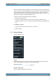
3. Make sure that the signals, the trigger, and the acquisition are set up correctly. The
following menus are available in XY-mode:
● "Vertical", see Chapter 2.2, "Vertical Setup", on page 40.
● "Horizontal", see Chapter 2.3, "Horizontal Setup", on page 43.
● "Trigger", see Chapter 2.5, "Trigger", on page 47.
● "Acquire", see Chapter 2.4, "Acquisition Control", on page 45.
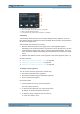
To analyze the signal in XY-mode, you can use cursor measurements. You can select
vertical or horizontal cursors, couple the cursor lines or set them to screen. All other
cursor settings are not relevant for measuring the XY-diagram.
Description of settings
Source X
Defines the signal that supplies the x-values of the XY-diagram, replacing the usual
time base. The source can be any of the active analog channels.
Source Y
Defines the signal to be displayed in y-direction in an XY-diagram. The source can be
any of the active analog channels.
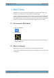
3.7 History (Option R&S RTH-K15)
The history option R&S RTH-K15 accesses the data of previous acquisitions and pro-
vides them for further analysis. Using this option, you can analyze, for example, packet
communication on serial buses, radar pulses, laser pulses, and signals that occur in
short bursts with long idle times.
History (Option R&S RTH-K15)