R&S®Scope Rider RTH Handheld Digital Oscilloscope User Manual (=J?Ü2) User Manual Test & Measurement 1326.1578.
This manual describes the following R&S®RTH models with firmware version 1.10 and higher: ● R&S®RTH1004 (1317.5000.K04) ● R&S®RTH1002 (1317.5000.K02) © 2016 Rohde & Schwarz GmbH & Co. KG Mühldorfstr. 15, 81671 München, Germany Phone: +49 89 41 29 - 0 Fax: +49 89 41 29 12 164 Email: info@rohde-schwarz.com Internet: www.rohde-schwarz.com Subject to change – Data without tolerance limits is not binding. R&S® is a registered trademark of Rohde & Schwarz GmbH & Co. KG.
Basic Safety Instructions Always read through and comply with the following safety instructions! All plants and locations of the Rohde & Schwarz group of companies make every effort to keep the safety standards of our products up to date and to offer our customers the highest possible degree of safety. Our products and the auxiliary equipment they require are designed, built and tested in accordance with the safety standards that apply in each case.
Basic Safety Instructions Symbol Meaning Symbol Meaning Caution ! Hot surface Alternating current (AC) Protective conductor terminal To identify any terminal which is intended for connection to an external conductor for protection against electric shock in case of a fault, or the terminal of a protective earth Direct/alternating current (DC/AC) Earth (Ground) Class II Equipment to identify equipment meeting the safety requirements specified for Class II equipment (device protected by double or rei
Basic Safety Instructions Operating states and operating positions The product may be operated only under the operating conditions and in the positions specified by the manufacturer, without the product's ventilation being obstructed. If the manufacturer's specifications are not observed, this can result in electric shock, fire and/or serious personal injury or death. Applicable local or national safety regulations and rules for the prevention of accidents must be observed in all work performed. 1.
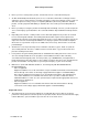
Basic Safety Instructions 6. The product may be operated only from TN/TT supply networks fuse-protected with max. 16 A (higher fuse only after consulting with the Rohde & Schwarz group of companies). 7. Do not insert the plug into sockets that are dusty or dirty. Insert the plug firmly and all the way into the socket provided for this purpose. Otherwise, sparks that result in fire and/or injuries may occur. 8.
Basic Safety Instructions 2. Before you move or transport the product, read and observe the section titled "Transport". 3. As with all industrially manufactured goods, the use of substances that induce an allergic reaction (allergens) such as nickel cannot be generally excluded.
Basic Safety Instructions 2. Adjustments, replacement of parts, maintenance and repair may be performed only by electrical experts authorized by Rohde & Schwarz. Only original parts may be used for replacing parts relevant to safety (e.g. power switches, power transformers, fuses). A safety test must always be performed after parts relevant to safety have been replaced (visual inspection, protective conductor test, insulation resistance measurement, leakage current measurement, functional test).
Instrucciones de seguridad elementales Waste disposal/Environmental protection 1. Specially marked equipment has a battery or accumulator that must not be disposed of with unsorted municipal waste, but must be collected separately. It may only be disposed of at a suitable collection point or via a Rohde & Schwarz customer service center. 2. Waste electrical and electronic equipment must not be disposed of with unsorted municipal waste, but must be collected separately. Rohde & Schwarz GmbH & Co.
Instrucciones de seguridad elementales Se parte del uso correcto del producto para los fines definidos si el producto es utilizado conforme a las indicaciones de la correspondiente documentación del producto y dentro del margen de rendimiento definido (ver hoja de datos, documentación, informaciones de seguridad que siguen). El uso del producto hace necesarios conocimientos técnicos y ciertos conocimientos del idioma inglés.
Instrucciones de seguridad elementales Símbolo Significado Símbolo Aviso: Cuidado en el manejo de dispositivos sensibles a la electrostática (ESD) Significado Distintivo de la UE para la eliminación por separado de dispositivos eléctricos y electrónicos Más información en la sección "Eliminación/protección del medio ambiente", punto 2. Advertencia: rayo láser Más información en la sección "Funcionamiento", punto 7.
Instrucciones de seguridad elementales 1. Si no se convino de otra manera, es para los productos Rohde & Schwarz válido lo que sigue: como posición de funcionamiento se define por principio la posición con el suelo de la caja para abajo, modo de protección IP 2X, uso solamente en estancias interiores, utilización hasta 2000 m sobre el nivel del mar, transporte hasta 4500 m sobre el nivel del mar. Se aplicará una tolerancia de ±10 % sobre el voltaje nominal y de ±5 % sobre la frecuencia nominal.
Instrucciones de seguridad elementales 6. Solamente está permitido el funcionamiento en redes de alimentación TN/TT aseguradas con fusibles de 16 A como máximo (utilización de fusibles de mayor amperaje solo previa consulta con el grupo de empresas Rohde & Schwarz). 7. Nunca conecte el enchufe en tomas de corriente sucias o llenas de polvo. Introduzca el enchufe por completo y fuertemente en la toma de corriente. La no observación de estas medidas puede provocar chispas, fuego y/o lesiones. 8.
Instrucciones de seguridad elementales Funcionamiento 1. El uso del producto requiere instrucciones especiales y una alta concentración durante el manejo. Debe asegurarse que las personas que manejen el producto estén a la altura de los requerimientos necesarios en cuanto a aptitudes físicas, psíquicas y emocionales, ya que de otra manera no se pueden excluir lesiones o daños de objetos. El empresario u operador es responsable de seleccionar el personal usuario apto para el manejo del producto. 2.
Instrucciones de seguridad elementales Reparación y mantenimiento 1. El producto solamente debe ser abierto por personal especializado con autorización para ello. Antes de manipular el producto o abrirlo, es obligatorio desconectarlo de la tensión de alimentación, para evitar toda posibilidad de choque eléctrico. 2. El ajuste, el cambio de partes, el mantenimiento y la reparación deberán ser efectuadas solamente por electricistas autorizados por Rohde & Schwarz.
Instrucciones de seguridad elementales 2. Las asas instaladas en los productos sirven solamente de ayuda para el transporte del producto por personas. Por eso no está permitido utilizar las asas para la sujeción en o sobre medios de transporte como p. ej. grúas, carretillas elevadoras de horquilla, carros etc. Es responsabilidad suya fijar los productos de manera segura a los medios de transporte o elevación.
Grundlegende Sicherheitshinweise Lesen und beachten Sie unbedingt die nachfolgenden Anweisungen und Sicherheitshinweise! Alle Werke und Standorte der Rohde & Schwarz Firmengruppe sind ständig bemüht, den Sicherheitsstandard unserer Produkte auf dem aktuellsten Stand zu halten und unseren Kunden ein höchstmögliches Maß an Sicherheit zu bieten. Unsere Produkte und die dafür erforderlichen Zusatzgeräte werden entsprechend der jeweils gültigen Sicherheitsvorschriften gebaut und geprüft.
Grundlegende Sicherheitshinweise Symbole und Sicherheitskennzeichnungen Symbol Bedeutung Achtung, allgemeine Gefahrenstelle Symbol Bedeutung EIN-/AUS (Versorgung) Produktdokumentation beachten Vorsicht beim Umgang mit Geräten mit hohem Gewicht Stand-by-Anzeige Gefahr vor elektrischem Schlag Gleichstrom (DC) Warnung vor heißer Oberfläche Wechselstrom (AC) Schutzleiteranschluss Gleichstrom/Wechselstrom (DC/AC) Erdungsanschluss Gerät entspricht den Sicherheitsanforderungen an die Schutzklasse II
Grundlegende Sicherheitshinweise Signalworte und ihre Bedeutung Die folgenden Signalworte werden in der Produktdokumentation verwendet, um vor Risiken und Gefahren zu warnen. kennzeichnet eine unmittelbare Gefährdung mit hohem Risiko, die Tod oder schwere Körperverletzung zur Folge haben wird, wenn sie nicht vermieden wird. kennzeichnet eine mögliche Gefährdung mit mittlerem Risiko, die Tod oder (schwere) Körperverletzung zur Folge haben kann, wenn sie nicht vermieden wird.
Grundlegende Sicherheitshinweise Elektrische Sicherheit Werden die Hinweise zur elektrischen Sicherheit nicht oder unzureichend beachtet, kann dies elektrischen Schlag, Brand und/oder schwere Verletzungen von Personen, unter Umständen mit Todesfolge, verursachen. 1. Vor jedem Einschalten des Produkts ist sicherzustellen, dass die am Produkt eingestellte Nennspannung und die Netznennspannung des Versorgungsnetzes übereinstimmen. Ist es erforderlich, die Spannungseinstellung zu ändern, so muss ggf.
Grundlegende Sicherheitshinweise 12. Wird ein Produkt ortsfest angeschlossen, ist die Verbindung zwischen dem Schutzleiteranschluss vor Ort und dem Geräteschutzleiter vor jeglicher anderer Verbindung herzustellen. Aufstellung und Anschluss darf nur durch eine Elektrofachkraft erfolgen. 13.
Grundlegende Sicherheitshinweise 5. Bei bestimmten Produkten, z.B. HF-Funkanlagen, können funktionsbedingt erhöhte elektromagnetische Strahlungen auftreten. Unter Berücksichtigung der erhöhten Schutzwürdigkeit des ungeborenen Lebens müssen Schwangere durch geeignete Maßnahmen geschützt werden. Auch Träger von Herzschrittmachern können durch elektromagnetische Strahlungen gefährdet sein.
Grundlegende Sicherheitshinweise 3. Zellen oder Batterien dürfen nicht kurzgeschlossen werden. Zellen oder Batterien dürfen nicht gefahrbringend in einer Schachtel oder in einem Schubfach gelagert werden, wo sie sich gegenseitig kurzschließen oder durch andere leitende Werkstoffe kurzgeschlossen werden können. Eine Zelle oder Batterie darf erst aus ihrer Originalverpackung entnommen werden, wenn sie verwendet werden soll. 4.
Grundlegende Sicherheitshinweise 3. Werden Produkte oder ihre Bestandteile über den bestimmungsgemäßen Betrieb hinaus mechanisch und/oder thermisch bearbeitet, können ggf. gefährliche Stoffe (schwermetallhaltiger Staub wie z.B. Blei, Beryllium, Nickel) freigesetzt werden. Die Zerlegung des Produkts darf daher nur von speziell geschultem Fachpersonal erfolgen. Unsachgemäßes Zerlegen kann Gesundheitsschäden hervorrufen. Die nationalen Vorschriften zur Entsorgung sind zu beachten. 4.
Consignes de sécurité fondamentales Lisez et respectez impérativement les instructions et consignes de sécurité suivantes Les usines et sites du groupe Rohde & Schwarz veillent à la conformité des produits du groupe avec les normes de sécurité en vigueur dans un souci constant de garantir aux clients le plus haut niveau de sécurité possible. Nos produits ainsi que les accessoires nécessaires sont fabriqués et testés conformément aux règles de sécurité en vigueur.
Consignes de sécurité fondamentales Symboles et marquages de sécurité Symbole Signification Avis, source générale de danger Symbole Signification MARCHE / ARRET (tension d’alimentation) Se référer à la documentation produit Attention lors de la manipulation d’appareils ayant un poids élevé Indicateur de veille Risque de choc électrique Courant continu (CC) Avertissement, surface chaude Courant alternatif (CA) Borne de conducteur de protection Courant continu/alternatif (CC/CA) Borne de mise à l
Consignes de sécurité fondamentales Mots d’alerte et significations Les mots d’alerte suivants sont utilisés dans la documentation produit pour avertir des risques et dangers. Indique une situation dangereuse immédiate qui, si elle n’est pas évitée, comporte un risque élevé de blessures graves ou mortelles. Indique une situation dangereuse possible qui, si elle n’est pas évitée, comporte un risque modéré de blessures (graves) ou mortelles.
Consignes de sécurité fondamentales Sécurité électrique Si les consignes relatives à la sécurité électrique ne sont pas ou sont insuffisamment respectées, il peut s’ensuivre des chocs électriques, des incendies et/ou des blessures graves pouvant éventuellement entraîner la mort. 1. Avant chaque mise sous tension du produit, il faut s’assurer que la tension nominale réglée sur le produit correspond à la tension nominale du réseau électrique.
Consignes de sécurité fondamentales 12. Si un produit est connecté de façon stationnaire, établir avant toute autre connexion le raccordement du conducteur de protection local et du conducteur de protection du produit. L’installation et le raccordement ne peuvent être effectués que par un électricien ou électronicien qualifié. 13.
Consignes de sécurité fondamentales 5. Selon les fonctions, certains produits, tels que des systèmes de radiocommunication RF, peuvent produire des niveaux élevés de rayonnement électromagnétique. Étant donné la vulnérabilité de l’enfant à naître, les femmes enceintes doivent être protégées par des mesures appropriées. Les porteurs de stimulateurs cardiaques peuvent également être menacés par les rayonnements électromagnétiques.
Consignes de sécurité fondamentales 1. Les cellules ne doivent être ni démontées, ni ouvertes, ni réduites en morceaux. 2. Ne jamais exposer les cellules ou batteries à la chaleur ou au feu. Ne pas les stocker dans un endroit où elles sont exposées au rayonnement direct du soleil. Tenir les cellules et batteries au sec. Nettoyer les raccords sales avec un chiffon sec et propre. 3. Ne jamais court-circuiter les cellules ou batteries.
Consignes de sécurité fondamentales 2. Au terme de sa durée de vie, un produit ne peut pas être éliminé avec les déchets ménagers normaux, mais doit être collecté séparément. Rohde & Schwarz GmbH & Co. KG a développé un concept d’élimination des déchets et assume toutes les obligations en matière de reprise et d’élimination, valables pour les fabricants au sein de l’UE. Veuillez vous adresser à votre centre de service après-vente Rohde & Schwarz pour éliminer le produit de manière écologique. 3.
Customer Support Technical support – where and when you need it For quick, expert help with any Rohde & Schwarz equipment, contact one of our Customer Support Centers. A team of highly qualified engineers provides telephone support and will work with you to find a solution to your query on any aspect of the operation, programming or applications of Rohde & Schwarz equipment.
R&S®Scope Rider RTH Contents Contents 1 Getting Started....................................................................................... 9 1.1 Preface........................................................................................................................... 9 1.1.1 Key Features...................................................................................................................9 1.1.2 Input Isolation...................................................................
R&S®Scope Rider RTH Contents 2.3 Horizontal Setup..........................................................................................................43 2.4 Acquisition Control.....................................................................................................45 2.5 Trigger..........................................................................................................................47 2.5.1 General Trigger Settings....................................................
R&S®Scope Rider RTH Contents 3.7.1 History Settings............................................................................................................. 91 3.7.2 Displaying History Data.................................................................................................92 3.7.3 Analyzing History Data..................................................................................................94 4 Mask Testing....................................................................
R&S®Scope Rider RTH Contents 7.1 General Protocol Settings........................................................................................ 120 7.2 I2C (Option R&S RTH-K1).........................................................................................121 7.2.1 The I²C Protocol.......................................................................................................... 121 7.2.2 I2C Configuration Settings...................................................................
R&S®Scope Rider RTH Contents 11.1 LAN Connection........................................................................................................ 153 11.2 USB connection........................................................................................................ 155 11.3 Wireless LAN Connection (Option R&S RTH-K200).............................................. 155 11.4 Web Interface (Option R&S RTH-K201)...................................................................
R&S®Scope Rider RTH Contents 12.8.4 UART/RS-232/RS-422/RS-485 (Option R&S RTH-K2).............................................. 223 12.9 Logic Analyzer (R&S RTH-B1 MSO)........................................................................ 226 12.10 Documenting Results............................................................................................... 229 12.10.1 Screenshots................................................................................................................
R&S®Scope Rider RTH Getting Started Preface 1 Getting Started 1.1 Preface 1.1.1 Key Features The R&S RTH is the perfect multi-purpose tool for the lab and in the field. Outstanding key features are: ● Full isolation of all channels and interfaces ● CAT IV 600 V / CAT III 1000 V safety rating ● Bandwidth 60 MHz to 500 MHz with 5 GS/s sampling rate ● Acquisition speed up to 50.
R&S®Scope Rider RTH Getting Started Preface Figure 1-1: Isolation scheme of the R&S RTH The input isolation has several advantages: ● You can measure independently floating signals simultaneously. ● The risk of causing a short circuit while measuring multiple signals is reduced substantially. ● When measuring signals with different grounds, the induced ground currents are kept to a minimum. 1.1.
R&S®Scope Rider RTH Getting Started Preface For measurements performed on circuits directly connected to the low-voltage installation by a standard socket outlet, for example, household appliances and portable tools. ● CAT III: For measurements performed in the building installation, such as junction boxes, circuit breakers, distribution boards, and equipment with permanent connection to the fixed installation.
R&S®Scope Rider RTH Getting Started Preface this manual is delivered with the instrument in printed form. Editions in other languages, as well as newest version of the English one, are available on the product website. ● User Manual The user manual describes all instrument modes and functions in detail. It also provides an introduction to remote control and a complete description of the remote control commands with programming examples.
R&S®Scope Rider RTH Getting Started Preparing for Use reasonable protection against harmful interference when the equipment is operated in a commercial environment. This equipment generates, uses, and can radiate radio frequency energy and, if not installed and used in accordance with the instruction manual, may cause harmful interference to radio communications.
R&S®Scope Rider RTH Getting Started Preparing for Use 1. Inspect the package for damage. If the packaging material shows any signs of stress, notify the carrier as well as your Rohde & Schwarz service center. Keep the package and cushioning material for inspection. Keep a damaged package and the cushioning material until the contents have been checked for completeness and the instrument has been tested. 2.
R&S®Scope Rider RTH Getting Started Preparing for Use Risk of electrical shock during battery replacement ● Disconnect power supply, probes, test leads and all other cables before opening the battery cover. ● Use only the specified Li-Ion battery pack, which is delivered with the instrument. You can order additional battery packs at Rohde & Schwarz, see Data Sheet for order number. ● Do not operate the instrument with the battery cover open.
R&S®Scope Rider RTH Getting Started Preparing for Use If the instrument is on, the battery status is shown on the display. Replace used batteries periodically by new batteries after 24 months of usage. Observe the safety regulations in the "Batteries and rechargeable batteries/cells" chapter in the "Basis Safety Instructions" brochure, which is delivered with the instrument. 1.2.3 Powering On/Off ► Press the POWER key to switch the instrument on or off.
R&S®Scope Rider RTH Getting Started Preparing for Use 1.2.5 EMI Suppression Electromagnetic Interference (EMI) may affect the measurement results. To suppress generated Electromagnetic Interference: ● Use suitable shielded cables of high quality. For example use double-shielded RF and LAN cables. ● Always terminate open cable ends. ● Note the EMC classification in the data sheet. User Manual 1326.1578.
R&S®Scope Rider RTH Getting Started Instrument Tour 1.3 Instrument Tour 1.3.
R&S®Scope Rider RTH Getting Started Instrument Tour Figure 1-4: Front panel of the R&S RTH1004 1 2 3 4 5 6 7 8 9 10 11 12 13 = = = = = = = = = = = = = Touch display Waveform setup with AUTOSET, reset to default with PRESET Analysis functions Mode selection Save/Recall Instrument settings Power on/off Navigation controls Horizontal settings Run/stop acquisition and trigger settings Acquisition settings Screenshot and documentation output Channels and vertical settings For a description of the keys, see
R&S®Scope Rider RTH Getting Started Instrument Tour 1.3.2 Top View The R&S RTH1002 has two BNC input connectors CH1 and CH2, and two 4mm banana plug inputs for various multimeter measurements. The channel inputs have double channel-to-channel isolation that allows for independent floating measurements at each input. The DMM input is fully isolated from scope inputs, interfaces and ground. Figure 1-5: Top view of R&S RTH1002 The R&S RTH1004 has four BNC input connectors CH1, CH2, CH3, CH4.
R&S®Scope Rider RTH Getting Started Instrument Tour Shock hazard caused by high voltages To avoid electrical shock and personal injury, and to prevent damage to the instrument or any other products connected to it, observe the following: ● Do not apply input voltages above the rating of the instrument and the accessories. ● Use only probes, test leads, and adapters that comply with the measurement category (CAT) of your measurement task.
R&S®Scope Rider RTH Getting Started Instrument Tour 1 2 3 4 5 = = = = = LAN USB type B for remote control Probe compensation USB type A for flash drive Logic probe connector Risk of injury or instrument damage Always close the lids of the communication ports and DC input when they are not in use. LAN connector RJ-45 connector to connect the instrument to a Local Area Network (LAN). It supports up to 100 Mbit/s.
R&S®Scope Rider RTH Getting Started Instrument Tour 1.3.4 Left View 1 = DC Input 2 = Kensington lock slot DC Input Connector for the power adapter to charge the battery. Kensington lock slot The Kensington lock is used to secure the instrument against theft. 1.3.5 Display Overview In the most important modes scope, mask and XY, the display shows the following information. User Manual 1326.1578.
R&S®Scope Rider RTH Getting Started Operating Basics 1 2 3 4 5 6 7 8 9 = = = = = = = = = Measurement results, depends on the mode and the selected measurement Time scale (horizontal scale, in s/division) Trigger type, trigger source, and trigger mode Capture status Battery status and AC connectivity for battery charging; date and time Trigger level Trigger position Channel marker indicate the ground levels.
R&S®Scope Rider RTH Getting Started Operating Basics 1.4.1.1 Using the Touchscreen Using the touchscreen of the R&S RTH is as easy as using your mobile phone. To open the menu, tap the "Menu" button - that is the R&S logo in the right bottom corner of the display. Figure 1-7: Open the menu and select a menu item User Manual 1326.1578.
R&S®Scope Rider RTH Getting Started Operating Basics Figure 1-8: Switch on or off (left) and select a parameter value (right) Figure 1-9: Enter numerical value and unit 1.4.1.2 Using the Navigation Wheel In addition or alternatively to the touchscreen, you can use the wheel to control the R&S RTH. User Manual 1326.1578.
R&S®Scope Rider RTH Getting Started Operating Basics When using the wheel, always observe the position of the focus - the orange frame or other highlighting that marks the active object on the screen. ● ● If the focus is on the menu button or somewhere in the menu or dialogs: – Turn the wheel to move the focus. – Press the wheel button to apply the selection.
R&S®Scope Rider RTH Getting Started Operating Basics Figure 1-10: Open the menu and select a menu item Set numerical value using the wheel 1. Set the focus to the required setting and press the wheel button once. 2. Turn the wheel until the required value is shown. 3. Press BACK. User Manual 1326.1578.
R&S®Scope Rider RTH Getting Started Operating Basics Figure 1-11: Set numerical value using the wheel Data entry using wheel and keypad You can enter enter precise numerical values on the keypad. See also Figure 1-12. 1. Set the focus to the required setting and press the wheel button twice. 2. Turn the wheel until the focus is on the required number. 3. Press the wheel button. 4. Turn the wheel until the focus is on the required unit. 5. Press the wheel button. User Manual 1326.1578.
R&S®Scope Rider RTH Getting Started Operating Basics Figure 1-12: Enter numerical value and unit in the keypad The SHIFT button toggles the wheel focus in the keypad. If the focus is on the entry field, turning the wheel changes the value. If the focus is in the lower part, the wheel selects numbers and unit. User Manual 1326.1578.
R&S®Scope Rider RTH Getting Started Operating Basics 1.4.1.3 Using Front Panel Keys For an overview of the front panel keys, see Figure 1-4 Key Short press Long press AUTOSET analyses the active channels, adjusts the instrument settings, and displays stable waveforms. PRESET sets the instrument to the default factory state. MEAS starts or stops the last configured automatic measurements. Opens or closes the "Meas" dialog to configure the measurements.
R&S®Scope Rider RTH Getting Started Operating Basics Key Short press Long press Open or close the "Mode", "File" or "Setup" dialog, respectively. All R&S RTH: Outputs measurement documentation: saves a screenshot, waveform data, results, logger record, instrument settings, and/or text comment. You can select the data for output. Opens or closes the "Screenshot" dialog to configure the documentation output.
R&S®Scope Rider RTH Getting Started Operating Basics Key Short press Long press LEVEL activates the trigger level to be set using the wheel. If the trigger type has two trigger levels, pressing the key toggles the upper and lower levels. ACQUIRE opens or closes the "Acquire" dialog to adjust the acquisition mode. POWER key: switches the power on or off 1.4.2 Selecting the Mode A mode comprises all settings and functions that are needed to perform a measurement task.
R&S®Scope Rider RTH Getting Started Operating Basics 1.4.3 Displaying an Unknown Signal The R&S RTH can display unknown, complex signals automatically. The AUTOSET function analyzes the enabled channel signals, and adjusts the horizontal, vertical, and trigger settings to display stable waveforms. 1. Press the PRESET key. PRESET sets the instrument to a default factory state. The previous user-defined configuration is removed and all channels except for channel 1 are disabled. 2. Press the AUTOSET key.
R&S®Scope Rider RTH Getting Started Operating Basics To show information on a setting If a dialog and the help window are open, you can easily call the information on each setting of the dialog. ► Tap the setting's name. The corresponding help topic is displayed. If you tap the switch or the entry field, you can adjust the setting without closing the help window. To close the help window ► Tap the "Close" icon in the upper right corner of the help window, or press BACK. User Manual 1326.1578.
R&S®Scope Rider RTH Getting Started Operating Basics 1.4.4.2 Using the Help Window The help window has several tabs: ● "View": shows the selected help topic. ● "Contents": contains a table of help contents. ● "Index": contains index entries to search for help topics. ● "Search": provides text search. The help toolbar provides the following buttons: ● Up and down arrows: browse the topics in the order of the table of contents. Up = previous topic, down = next topic.
R&S®Scope Rider RTH Getting Started Maintenance To find a string of several words, enclose it in quotation marks. For example, a search for "trigger mode" finds all topics with exactly "trigger mode". A search for trigger mode finds all topics that contain the words trigger and mode. 4. Tap the Enter key. A list of search results is displayed. 5. To refine the search, use "Match Whole Word" and "Match Case", and tap "Start Search". 1.5 Maintenance The instrument does not need a periodic maintenance.
R&S®Scope Rider RTH Getting Started Maintenance All instrument configuration data and user data are stored on the microSD card. In addition, a fallback firmware is stored on the microSD card to boot the instrument if an update failed. If you use the instrument in a secured environment, you can remove the microSD card before the instrument leaves this area. The microSD card slot is under the right lid under the battery pack. You can also change the microSD card if you need more memory.
R&S®Scope Rider RTH Waveform Setup Connecting Probes 2 Waveform Setup 2.1 Connecting Probes Shock hazard caused by high voltages Make sure to set the attenuation factor on the instrument according to the probe being used. Otherwise, the measurement results do not reflect the actual voltage level, and you might misjudge the actual risk. 1. Connect the probe(s) first to the channel input(s) at the top of the instrument, and then to the DUT. 2. Press and hold the CH key of the used input. 3.
R&S®Scope Rider RTH Waveform Setup Vertical Setup 2.2 Vertical Setup The controls and parameters of the vertical system are used to scale and position the waveform vertically. 1. To set vertical scale and position, use the RANGE and POS keys. 2. To adjust other vertical settings, select "Vertical" in the main menu. As long as the "Vertical" menu is open, the probe settings of active channels are shown on top of the display.
R&S®Scope Rider RTH Waveform Setup Vertical Setup Channel Index Selects the channel to be set up. All settings in the channel menu belong to the selected channel. You can also press the channel key to select a channel. A long press of the channel key opens the correspondent channel menu. State Switches the selected channel on or off. Remote command: CHANnel:STATe on page 160 Coupling Selects the connection of the input signal.
R&S®Scope Rider RTH Waveform Setup Vertical Setup Remote command: CHANnel:BANDwidth on page 163 Invert Turns the inversion of the signal amplitude on or off. To invert means to reflect the voltage values of all signal components against the ground level. Inversion affects only the display of the signal but not the trigger. For example: if the oscilloscope triggers on the rising edge, the trigger is not changed by inversion, but the actually rising edge is displayed as falling edge.
R&S®Scope Rider RTH Waveform Setup Horizontal Setup "Find Threshold" Analyzes the signal and sets the threshold to 50% of the amplitude. "Show Threshold" Shows the threshold level on the display. RANGE keys The vertical RANGE keys set the vertical scale (vertical sensitivity) of the selected waveform. Remote command: CHANnel:SCALe on page 161 CHANnel:RANGe on page 161 POS keys Move the selected signal up or down in the diagram.
R&S®Scope Rider RTH Waveform Setup Horizontal Setup t=0 T Horiz. position from right ref. point (> 0) Horiz. position from middle ref. point (> 0) Horiz. position from left ref. point (< 0) Reference point = Left Reference point = Middle Reference point = Right Description of settings Time Scale Sets the time scale of the horizontal axis for all signals, in seconds per division. The value is shown in the top information bar. Increase the scale to see a longer part of the waveform.
R&S®Scope Rider RTH Waveform Setup Acquisition Control Reference Point Defines the time reference point in the diagram. You can set the reference point in the middle, or to the right to see the signal before the trigger, or the the left to see the signal after the trigger. Remote command: TIMebase:REFerence on page 165 2.4 Acquisition Control Acquisition settings define the processing of the captured samples in the instrument.
R&S®Scope Rider RTH Waveform Setup Acquisition Control "Peak Detect" The minimum and the maximum of n samples are recorded as waveform points, the other samples are discarded. Thus the instrument can detect fast signal peaks at slow time scale settings that would be missed with other acquisition modes. "High Resolution" The average of n captured sample points is recorded as one waveform point. Averaging reduces the noise, the result is a more precise waveform with higher vertical resolution.
R&S®Scope Rider RTH Waveform Setup Trigger 2.5 Trigger Triggering means to capture the interesting part of the relevant waveforms. Choosing the right trigger type and configuring all trigger settings correctly allows you to detect various incidents in signals. A trigger occurs if the trigger conditions are fulfilled. The instrument acquires continuously and keeps the sample points to fill the pretrigger part of the waveform record.
R&S®Scope Rider RTH Waveform Setup Trigger Description of settings Trigger Mode The trigger mode determines the behavior of the instrument if no trigger occurs, and also the number of acquired waveforms when a trigger occurs. "Auto" The instrument triggers repeatedly after a time interval if the trigger conditions are not fulfilled. If a real trigger occurs, it takes precedence. This mode helps to see the waveform even before the trigger is set.
R&S®Scope Rider RTH Waveform Setup Trigger For most trigger types, analog and digital channels can be used as trigger source. Digital channels require option R&S RTH-B1. For video, runt and slew rate trigger, only analog channels are available. Remote command: TRIGger:SOURce on page 169 Trigger Level Sets the trigger voltage level. For the Video/TV trigger, the trigger level is the threshold of the sync pulse. Make sure that the trigger level crosses the synchronizing pulses of the video signal.
R&S®Scope Rider RTH Waveform Setup Trigger Remote command: TRIGger:HOLDoff:EVENts on page 170 Min Time / Max Time ← Holdoff Mode Set the time limits for random holdoff time. For each acquisition, the instrument selects a new random holdoff time from the specified range. Remote command: TRIGger:HOLDoff:MIN on page 170 TRIGger:HOLDoff:MAX on page 170 Noise Reject Enables a hysteresis to avoid unwanted trigger events caused by noise oscillation around the trigger level.
R&S®Scope Rider RTH Waveform Setup Trigger 2.5.3 Glitch Trigger The glitch trigger detects pulses shorter or longer than a specified time. It identifies deviation from the nominal data rate and helps to analyze causes of even rare glitches and their effects on other signals. Description of settings Polarity Sets the pulse polarity, that is the direction of the first pulse slope. You can trigger on: ● ● ● Positive going pulses. The width is defined from the rising to the falling edge.
R&S®Scope Rider RTH Waveform Setup Trigger 2.5.4 Width Trigger The width trigger compares the measured pulse width (duration of a pulse) with a given time limit. It detects pulses with an exact pulse width, pulses shorter or longer than a given time, as well as pulses inside or outside the allowable time range. The pulse width is measured at the trigger level. Using the width trigger, you can define the pulse width more precisely than with the glitch trigger.
R&S®Scope Rider RTH Waveform Setup Trigger min max 1 min max 2 Figure 2-5: Pulse width is inside or outside a range 1 = Inside, pulse > min width AND pulse < max width 2 = Outside, pulse < min width OR pulse > max width ±Δ 1 ±Δ 2 Figure 2-6: Pulse width is equal or unequal to a given width, with optional tolerance 1 = Equal, pulse > width - Δ AND pulse < width + Δ 2 = Unequal, pulse < width - Δ OR pulse > width + Δ Remote command: TRIGger:WIDTh:RANGe on page 172 Width Sets the width for comparis
R&S®Scope Rider RTH Waveform Setup Trigger The instrument triggers on the line start - the horizontal sync pulse. You can trigger on all lines, or specify a line number. You can also trigger on the field or frame start. 2.5.5.1 Standard TV Trigger Settings Access: SETUP key > "Trigger Type" = "Video/TV" Standard Selects the TV standard or "Custom" for user-defined signals. The standards PAL, PAL-M, NTSC and SECAM are available in the instrument firmware.
R&S®Scope Rider RTH Waveform Setup Trigger Mode Selects the lines or fields on which the instrument triggers. Available modes depend on the scanning system, which is used bei the selected standard. "All fields" Triggers on the first video line of the frame (progressive scanning) or field (interlaced scanning), for example, to find amplitude differences between the fields. "Odd fields / Even fields" Triggers on the first video line of the odd or even field.
R&S®Scope Rider RTH Waveform Setup Trigger Pulse Type Sets the type of the sync pulse, either bi-level sync pulse (usually used in SDTV signals), or tri-level sync pulse (used in HDTV signals). Figure 2-9: Bi-level (left) and tri-level (right) sync pulses This setting is available for user-defined video signals if "Standard" is set to "Custom". Line Period Sets the duration of a line, the time between two successive sync pulses.
R&S®Scope Rider RTH Waveform Setup Trigger This setting is available for user-defined video signals if "Standard" is set to "Custom". Scan Sets the scanning system. This setting is available for user-defined video signals if "Standard" is set to "Custom". "Interlaced" Interlace scanning uses two fields to create a frame. One field contains all the odd lines (odd, first, or upper filed), the other contains all the even lines of the image (even, second, or lower field).
R&S®Scope Rider RTH Waveform Setup Trigger Figure 2-11: Pattern definition The current threshold is displayed for each channel. Tap "Find Level" to determine a useful threshold for all active channels. The switches define the required state of each channel and set the logical combination: "1" The signal value is above the defined threshold. "0" The signal value is below the defined threshold. "X" The signal state does not matter.
R&S®Scope Rider RTH Waveform Setup Trigger "Equal" If the pattern is true for the time "Pattern Width" ± Δt (Tolerance), the trigger occurs. "Unequal" If the pattern is true for a time shorter than "Pattern Width" - Δt OR longer than "Pattern Width" + Δt, the trigger occurs. "Inside" If the pattern is true for a time between "Min Pattern Width" and "Max Pattern Width", the trigger occurs.
R&S®Scope Rider RTH Waveform Setup Trigger Clock Slope Sets the edge of the clock at which the instrument checks the signal states: at the rising edge, the falling adge, or at both edges. Remote command: TRIGger:STATe:CSOurce:EDGE on page 177 Set Pattern Defines the pattern: the states of the input channels and their logical combination. If R&S RTH-B1 is installed, active digital channels are also included in the pattern definition. For details, see Chapter 2.5.
R&S®Scope Rider RTH Waveform Setup Trigger Description of settings Upper Trigger Level / Lower Trigger Level Set the upper and lower voltage thresholds for the runt trigger. The levels define the minimum and maximum runt amplitudes. You can also press the LEVEL key to toggle the upper and lower levels, and turn the wheel to adjust the focused level. If the focus is on a trigger level, pressing the wheel also toggles the levels.
R&S®Scope Rider RTH Waveform Setup Trigger Remote command: TRIGger:RUNT:WIDTh on page 178 ±Tolerance Sets a tolerance range Δt to the specified Runt Width if the comparison range is equal or unequal. Remote command: TRIGger:RUNT:DELTa on page 178 Min Runt Width / Max Runt Width Set the lower and upper time limits if "Inside" or "Outside" is set for comparison. 2.5.
R&S®Scope Rider RTH Waveform Setup Trigger Description of settings Upper Trigger Level / Lower Trigger Level Set the upper and lower voltage thresholds for the slew rate trigger. The time measurement starts when the signal crosses the first trigger level - the upper or lower level depending on the selected slope - and stops when the signal crosses the second level.
R&S®Scope Rider RTH Waveform Setup Trigger ±Tolerance Sets a tolerance range Δt to the specified Time if the comparison range is equal or unequal. Remote command: TRIGger:SLEW:DELTa on page 180 Min Time / Max Time Set the lower and upper time limits if "Inside" or "Outside" is set for comparison. 2.5.10 Data2Clock Trigger (R&S RTH-K19) With the Data2Clock trigger - also known as setup/hold trigger - you can analyze the relative timing between two signals: a data signal and the synchronous clock signal.
R&S®Scope Rider RTH Waveform Setup Trigger Clock Slope Sets the edge of the clock signal: rising, falling, or both edges. The time reference point for the setup and hold time is the crossing point of the clock edge and the trigger level. Remote command: TRIGger:DATatoclock:CSOurce:EDGE on page 181 Data Source Selects the input channel of the data signal. Remote command: TRIGger:DATatoclock:DSOurce[:VALue] on page 181 Trigger on Setup & Hold Selects how a violation of the setup and hold time is handled.
R&S®Scope Rider RTH Waveform Setup Trigger Description of settings Figure 2-16: Serial Pattern Trigger Clock Source Selects the input channel of the clock signal. Remote command: TRIGger:SPATtern:CSOurce[:VALue] on page 182 Clock Slope Sets the edge at which the data value is sampled. ● Rising edge ● Falling edge ● Rising and falling edges are considered (double data rate).
R&S®Scope Rider RTH Waveform Setup Trigger Remote command: TRIGger:SPATtern:PATTern on page 183 Bit Order Defines if the data words start with msb (most significant bit) or lsb (least significant bit). Remote command: TRIGger:SPATtern:ORDer on page 183 2.5.12 Timeout Trigger (R&S RTH-K19) The timeout trigger checks if the signal stays above or below the trigger level for a specified time lapse. In other words, the trigger occurs if the signal does not cross the trigger level during the specified time.
R&S®Scope Rider RTH Waveform Setup Trigger Description of settings Figure 2-17: Timeout Trigger Range Selects the relation of the signal level to the trigger level: "Stays High" The signal level stays above the trigger level. "Stays Low" The signal level stays below the trigger level. "High or Low" The signal level stays above or below the trigger level. Remote command: TRIGger:TIMeout:RANGe on page 184 Time Defines the time limit for the timeout at which the instrument triggers.
R&S®Scope Rider RTH Waveform Setup Trigger Description of settings Figure 2-18: Interval Trigger Slope Sets the edge for the trigger. You can analyze the interval between positive edges or between negative edges. Remote command: TRIGger:INTerval:SLOPe on page 186 Range Defines how the time range of an interval is defined. The comparisons are the same as for the width trigger, see "Range" on page 52.
R&S®Scope Rider RTH Waveform Setup Trigger 2.5.14 Window Trigger (R&S RTH-K19) The window trigger checks the signal run in relation to a "window" that is formed by the upper and lower voltage levels. The trigger occurs, if the waveform enters or leaves the window, or if the waveform stays inside or outside for a defined time range. With the window trigger, you can display longer transient effects.
R&S®Scope Rider RTH Waveform Setup Trigger Range Selects how the time limit of the window is defined. Time conditioning is available for the vertical conditions "Stay Inside" and "Stay Outside". "Longer" Triggers if the signal crosses the upper or lower level after the specified "Width" time is reached. "Shorter" Triggers if the signal crosses the upper or lower level before the specified "Width" time is reached.
R&S®Scope Rider RTH Waveform Analysis Zoom 3 Waveform Analysis 3.1 Zoom The zoom magnifies a part of the waveform in order to view more details with a maximum zoom factor of 100. To activate the zoom: ► Press the ZOOM key. To adjust the zoom using the wheel: 1. Check if the zoom has the focus - an orange frame on the zoom indicator. If not, press the ZOOM key. 2. Turn the wheel to adjust the position of the zoom area. 3. Press the wheel to toggle the setting. 4. Turn the wheel to adjust the zoom factor.
R&S®Scope Rider RTH Waveform Analysis Zoom Figure 3-1: Zoomed waveform and zoom indicator with focus on zoom factor Figure 3-2: Zoom indicator with focus on zoom position To analyze the zoomed signal, you can use cursor measurements. Description of settings Enabled Enables or disables the zoom. Remote command: ZOOM:ENABle on page 187 Scale Sets the time scale of the zoomed waveform.
R&S®Scope Rider RTH Waveform Analysis Automatic Measurements Note: The zoom overview also considers the horizontal position of the trigger point. If the horizontal position is ≠ 0 and thus the trigger point is not in the middle, the zoom area in the overview is also shifted, even if the zoom position is 0. Remote command: ZOOM:POSition on page 188 3.2 Automatic Measurements You can perform up to four different measurements simultaneously.
R&S®Scope Rider RTH Waveform Analysis Automatic Measurements 3.2.2.1 Time Measurements Meas. type Symbol Description Period T Time of the first period, measured on the 50% level. The measurement requires at least one complete period of the signal. in s Frequency f in Hz Graphic / formula Source T Analog, math, reference, digital f=1/T T Analog, math, reference, digital 50% Frequency of the signal, reciprocal value of the measured first period.
R&S®Scope Rider RTH Waveform Analysis Automatic Measurements Meas. type Symbol Description Graphic / formula Delay Δt Time difference between two slopes of the same or different waveforms, measured on the 50% level. S1 in s Source 2 sources: analog, math, reference, digital t S2 ∡ Phase in ° Phase difference between two waveforms, measured on the 50% level. Phase = Δt / T * 360° 2 sources: S1 analog, math, reference, digital 0% 100% t S2 3.2.2.
R&S®Scope Rider RTH Waveform Analysis Automatic Measurements Meas. type Symbol Description Base level Base Low level of the displayed waveform the lower maximum of the sample distribution. The measurement requires at least one complete period of the signal. Graphic / formula Source analog, math, reference Base Top level Top High level of the displayed waveform the upper maximum of the sample distribution. The measurement requires at least one complete period of the signal.
R&S®Scope Rider RTH Waveform Analysis Automatic Measurements 3.2.2.3 Meas. type Counting Symbol Description Graphic / formula Sources Positive pulse count Number of positive pulses on the display. The mean value of the signal is determined. If the signal passes the mean value, an edge is counted. A positive pulse is counted if a rising edge and a following falling edge are detected. 1 2 3 N Analog, math, reference, digital Negative pulse count Number of negative pulses on the display.
R&S®Scope Rider RTH Waveform Analysis Automatic Measurements Meas. type Symbol Description Graphic / formula Sources Reactive power Q Reactive power is temporally stored in a system because of the inductive and capacitive elements. Im 2 sources: in var S φ Re P Power factor PF (no unit) Power factor is a measure of the system efficiency. The value varies between -1 and 1. analog, math, reference, digital Q PF = cos(φ) 2 sources: Im analog, math, reference, digital S φ P Q Re 3.2.
R&S®Scope Rider RTH Waveform Analysis Cursor Measurements Source / Source 2 Defines the waveform to be measured. For delay, phase, and power measurements, 2 sources are required. The sources can be any active input signal, math or reference waveform. Available source waveforms depend on the measurement type, see Chapter 3.2.2, "Measurement Types", on page 74. Remote command: MEASurement:SOURce on page 188 All off Disables all active measurements.
R&S®Scope Rider RTH Waveform Analysis Cursor Measurements tions of the cursor lines t1 and t2 are also measured. The results are time values and do not depend on any waveform, thus no source is required. ● CURSor:TDELta? on page 193 ● CURSor:ITDelta? on page 193 ● CURSor:X1Position on page 193 ● CURSor:X2Position on page 193 Horizontal cursors For horizontal cursors, the vertical values of the cursor positions y1 and y2 are measured. These are usually voltage or current values.
R&S®Scope Rider RTH Waveform Analysis Cursor Measurements If the measurement result is outside the measurement range and clipping occurs, the results are marked with < (underflow) or > (overflow). Adjust the vertical scale to get valid results. ● CURSor:MEASurement:RESult:ACTual? on page 194 ● CURSor:MEASurement:RESult:LIMit? on page 194 3.3.2 Settings for Cursor Measurements Access: "Cursor" menu State Enables or disables the cursor measurement.
R&S®Scope Rider RTH Waveform Analysis Cursor Measurements Remote command: CURSor:FUNCtion on page 191 Source Defines the source on which the cursor measurement is performed. The source can be any active analog or digital input signal, math waveform, or bus (requires option). The source setting is not available for the cursor type "Vertical", and for measurements in the XY-diagram.
R&S®Scope Rider RTH Waveform Analysis Mathematics Remote command: CURSor:SCReen on page 192 3.4 Mathematics A math waveform is a calculated waveform. You can calculate data out of one or two different sources using several predefined operations. ► To configure the math waveform, long-press the MATH key. ► To activate or deactivate the last configured math waveform, press the MATH key. ► To adjust vertical scale and position of the math waveform, use the RANGE and POS keys.
R&S®Scope Rider RTH Waveform Analysis Mathematics "S1 - S2" Subtraction: Subtracts the values of "Source 2" from the values of "Source 1". "S1 * S2" Multiplication: Multiplies the values of "Source 1" and "Source 2". "-S1," Inverse: Inverts all voltage values of "Source 1", i.e. all values are mirrored at the ground level. Thus, a positive voltage offset becomes negative. "|S1|" Abs. Value: Calculates the absolute value of "Source 1". All negative values are inverted to positive values.
R&S®Scope Rider RTH Waveform Analysis Reference Waveforms 3.5 Reference Waveforms To compare waveforms and analyze differences between waveforms, you can use a reference waveform. You can also save reference waveforms and load them for further use. The display of a reference waveform is independent from that of the source waveform; you can change the vertical scale and position To create and save a reference waveform 1. Set up the waveform that will be the reference. 2. Open the "Ref" menu. 3.
R&S®Scope Rider RTH Waveform Analysis Reference Waveforms Update Creates the reference waveform from the source waveform. Remote command: REFCurve:UPDate on page 196 State Activates the waveform and displays it. Remote command: REFCurve:STATe on page 196 CALCulate:MATH:STATe on page 195 Vertical Position Sets the vertical position of the reference waveform. You can also tap the waveform label "R" to set the focus to the reference waveform, and use the RANGE and POS keys to adjust the display.
R&S®Scope Rider RTH Waveform Analysis Reference Waveforms 3.5.2.1 Waveform Header Files The header files of XML and BIN waveform files are written in XML format. The header files of CSV waveform files are written in CSV format. You can open the header files and use their information for data analysis. CSV header files only contain the property names and values, one property per row. VerticalScale:0.05: HorizontalScale:5e-08: XML header files contain more information than CSV header files.
R&S®Scope Rider RTH Waveform Analysis XY-Diagram 3.5.2.2 Waveform Data Files The waveform data files are indicated by *Wfm.* in the file name. They contain the actual waveform data, the Y-values of the samples. Mostly, the Y-values are voltages: Y0; Y1; Y2; Y3; ... Before and after the waveform data, the instrument writes some presettling and postsettling samples.
R&S®Scope Rider RTH Waveform Analysis History (Option R&S RTH-K15) 3. Make sure that the signals, the trigger, and the acquisition are set up correctly. The following menus are available in XY-mode: ● ● ● ● "Vertical", see Chapter 2.2, "Vertical Setup", on page 40. "Horizontal", see Chapter 2.3, "Horizontal Setup", on page 43. "Trigger", see Chapter 2.5, "Trigger", on page 47. "Acquire", see Chapter 2.4, "Acquisition Control", on page 45.
R&S®Scope Rider RTH Waveform Analysis History (Option R&S RTH-K15) If history is enabled and an acquisition runs, the instrument stores the captured waveforms, processes the data and displays the current waveform. Each stored waveform is called a segment. When the acquisition is stopped, the history player is shown to access the stored segments, and to display and analyze them. When you start a new acquisition, the history is cleared and written anew.
R&S®Scope Rider RTH Waveform Analysis History (Option R&S RTH-K15) Note: If zoom or mathematics are active during acquisition, the actual number of stored segments may be less than the defined number. To avoid the decrease of stored waveforms, disable zoom and mathematics before you acquire the waveforms. You can enable zoom and mathematics later in stop mode and use them to analyze any of the history segments.
R&S®Scope Rider RTH Waveform Analysis History (Option R&S RTH-K15) 1 2 3 4 = = = = Timestamp, here: absolute time Index of the oldest, current, and newest (= 0) segment Slider to set the displayed segment Control buttons: Play, Step Forward, Step Back, and Repeat Timestamp The timestamp shows the time of the currently displayed history segment. Thus, the time relation between acquisitions is always available. More precisely, the timestamp is the time of the trigger event.
R&S®Scope Rider RTH Waveform Analysis History (Option R&S RTH-K15) b) Set the index of the first and the last segment that you want to see. See "Start Acquisition / Stop Acquisition" on page 92. c) In the history player window, tap the Play button. 4. To play back the segments repeatedly. a) Enable the Repeat button. b) Tap the Play button. 5. To access a particular segment, you can: ● ● Drag the slider in the history player window, until the required index number is shown.
R&S®Scope Rider RTH Mask Testing Mask Test Results 4 Mask Testing Masks are used to determine whether the amplitude of a signal remains within specified limits, e.g. to detect errors or test compliance of digital signals. A mask is specified by an upper and a lower limit line. The signal must run inside these limit lines, otherwise a mask violation occurs. A new mask is created from an existing signal: Mask limits are created by copying the waveform, and the limits are moved and stretched.
R&S®Scope Rider RTH Mask Testing Running Mask Tests Figure 4-1: Mask-mode-view 1 2 3 4 5 = = = = = Selected channel Number and percentage share of passed acquisitions Number and percentage share of failed acquisitions Number of tested acquisitions Test duration Remote commands for mask test results: ● MASK:CHANnel:RESult:PASS[:COUNt]? on page 203 ● MASK:CHANnel:RESult:PASS:PERCentage? on page 203 ● MASK:CHANnel:RESult:FAIL[:COUNt]? on page 203 ● MASK:CHANnel:RESult:FAIL:PERCentage? o
R&S®Scope Rider RTH Mask Testing Mask Settings 2. If you want to test a mathematical (math) waveform, generate a math waveform, see Chapter 3.4, "Mathematics", on page 84. 3. Select the "Mask" menu. 4. Select the mask channel that is assigned to the tested waveform. 5. To activate the mask, tap "State". Note: If the selected mask was used before, the stored mask is displayed. 6. To set the mask width, enter "Width X" and "Width Y". 7. Select the "Action on Violation". This action is applied to all masks.
R&S®Scope Rider RTH Mask Testing Mask Settings Figure 4-2: Mask settings Reset all Mask Results Resets all mask test results. Remote command: MASK:RST on page 202 Coupling If enabled, the settings of the selected mask are applied to all active masks when you tap "Create Mask". Mask Channel Selects the mask to be configured. If the selected mask has been created before, and it is active, the mask is shown on the display.
R&S®Scope Rider RTH Mask Testing Mask Settings Width X Changes the width of the mask in horizontal direction. The specified number of divisions in divisions is added to the positive x-values and subtracted from the negative x-values of the mask limits in relation to the mask center. Thus, the left half of the mask is pulled to the left, the right half is pulled to the right. To apply the changed value to an existing mask, tap "Create Mask".
R&S®Scope Rider RTH Multimeter Measurements Voltmeter (R&S RTH1004) 5 Multimeter Measurements The 4-channel R&S RTH1004 has 4 software-based voltmeters, which can measure in parallel. For each voltmeter you can select the source and measurement type. See Voltmeter (R&S RTH1004). The 2-channel R&S RTH1002 has a hardware-based digital multimeter with two separate banana plug inputs for various multimeter measurements.
R&S®Scope Rider RTH Multimeter Measurements Voltmeter (R&S RTH1004) Figure 5-1: One-voltmeter-view 1 2 3 4 5 6 7 8 9 10 11 12 13 = = = = = = = = = = = = = Measurement state. Manual: running measurement Probe settings Minimum value and time stamp Average value Maximum value and time stamp Warning sign, shows up if the measured value is higher than 30 V Bar graph displaying the measured value Measurement source (input channel). Selected source is highlighted. Measurement type (AC, DC or AC+DC).
R&S®Scope Rider RTH Multimeter Measurements Voltmeter (R&S RTH1004) Figure 5-2: Four-voltmeter-view 1 = Channel measured by the voltmeter 2 = Bar graph displaying the measured value 3 = Channel range Remote command: ● METer:READ? on page 205 ● METer:FETCh? on page 206 In meter mode, the keys behave slightly different from scope mode: ● The vertical RANGE and POS keys both adjust the range of the selected input channel. ● The MEAS key opens the "Meter" menu.
R&S®Scope Rider RTH Multimeter Measurements Voltmeter (R&S RTH1004) 5.1.3 Running Voltmeter Measurements 1. Select the "Vertical" menu and adjust the "Probe Setting" for all channels to be measured. See also "Probe Setting" on page 42. 2. If the 4-voltmeter-view is shown, switch to the one-voltmeter-view, see "Displaying voltmeters" on page 102. 3. Select the channel to be measured (no. 8 in Figure 5-1). 4. Select the measurement type (no. 9). 5. Activate the voltmeter (no. 12) 6.
R&S®Scope Rider RTH Multimeter Measurements Voltmeter (R&S RTH1004) Figure 5-3: Voltmeter settings Select Meter Selects one of the 4 voltmeters and displays its settings in the menu. State Switches the selected meter on or off. Remote command: METer:SENSe:STATe on page 204 Measure Type Sets the measurement type for the selected meter. Note: The AC coupling is activated if the selected channel is only used for AC measurements.
R&S®Scope Rider RTH Multimeter Measurements Digital Multimeter (R&S RTH1002) Input Signal Selects the channel which is measured by the selected meter. Remote command: METer:SENSe:SOURce on page 205 Relative Activates or deactivates relative measurement. If you activate this function, the currently measured value is taken as reference value. Instead of the bar graph, the reference value and the measured value are displayed (see Figure 5-4).
R&S®Scope Rider RTH Multimeter Measurements Digital Multimeter (R&S RTH1002) 5.2.1 Accessing the Meter Mode ► There are several ways to start the multimeter mode: ● Press the DMM key. ● Press the MODE key, and select "Meter". ● To start relative measurements, press the DMM REL key. The multimeter interface is displayed, and the measurement is started immediately. 5.2.2 Display and Control The multimeter display shows detailed results and setup icons.
R&S®Scope Rider RTH Multimeter Measurements Digital Multimeter (R&S RTH1002) 7 8 9 10 11 = = = = = Warning sign, shows up if the measured value is higher than 30 V Bar graph displaying the measured value Measurement type Activates or deactivates relative measurement Restarts the measurement and resets all values Remote command: ● METer:READ? on page 205 ● METer:FETCh? on page 206 In meter mode, the keys behave slightly different from scope mode: ● The vertical RANGE and POS keys adjust the m
R&S®Scope Rider RTH Multimeter Measurements Digital Multimeter (R&S RTH1002) Figure 5-6: Digital multimeter settings Meter Type Sets the measurement type for the multimeter.
R&S®Scope Rider RTH Multimeter Measurements Digital Multimeter (R&S RTH1002) Relative Activates or deactivates relative measurement. If you activate this function, the currently measured value is taken as reference value. Instead of the bar graph, the reference value and the measured value are displayed. You can also set a desired value as reference value, see "Reference / Reference Manual" on page 109. You can also activate or deactivate relative measurement by pressing DMM REL.
R&S®Scope Rider RTH Data Logging Logger Display 6 Data Logging The data logger records scope or meter data captured of up to 4 different measurements. The logging can last up to 23 days. The records are displayed as an on-screenchart and can be stored in 10 different slots. Using the "Zoom" and "Cursor" functions, logged data can be analyzed. 6.1 Accessing the Logger Mode 1. Press the MODE key. 2. Select "Logger". The logger interface is displayed.
R&S®Scope Rider RTH Data Logging Logging Data Figure 6-1: Logger display, view of all logged scope measurements 1 2 3 4 5 6 7 8 = = = = = = = = Logged measurements Latest values of the logged measurements (depends on logging type and measurement type) Time basis Memory slot Recording time Start time Upper and lower scaling value of each measurement Time stamp of the left side of the display Displaying logged measurements 1.
R&S®Scope Rider RTH Data Logging Logger Settings 1. Access the logger mode, see Chapter 6.1, "Accessing the Logger Mode", on page 110. 2. Select the "Logger" menu. 3. If data logging is running, press RUN/STOP to stop the logging. The logged data is stored automatically. You can only adjust the logger settings if logging is stopped. 4. Select the source that you want to log. 5. Select the sample rate. 6. Select the horizontal scale. By default, the horizontal scale is set to "auto".
R&S®Scope Rider RTH Data Logging Logger Settings Source Selects the logger source: "Scope" or "Meter". Remote command: LOGGer:SOURce on page 207 Sample Rate Selects the number of log samples per second. Remote command: LOGGer:TIMebase:SRATe on page 207 Horizontal Scale Selects the horizontal scale of the logged data. The horizontal scale is set to "auto" by default. In this case, all logged data is always displayed.
R&S®Scope Rider RTH Data Logging Analyzing Logged Data 6.5 Analyzing Logged Data You can analyze logged data using the "Cursor" and the "Zoom". To analyze logged data at a later time, the data is stored automatically, and you can load the stored data to the display. 6.5.1 Cursor To analyze logged data, you can use cursor measurements, see also Chapter 3.3, "Cursor Measurements", on page 80.
R&S®Scope Rider RTH Data Logging Analyzing Logged Data The logger cursor only allows you to set a "Cursor Value". You cannot define the cursor "Type" and "Source" as you can in the "Scope" and "Mask" mode because these settings are not relevant for logging. Description of settings Access: "Cursor" menu Figure 6-3: Cursor settings Enable Enables or disables the cursor measurement.
R&S®Scope Rider RTH Data Logging Analyzing Logged Data Figure 6-4: Logger cursor with summarized data 1 = Maximum value of cursor line 1 2 = Maximum value of cursor line 2 Remote command: LOGGer:CURSor:TYPE on page 208 Track scaling If enabled, the position of the cursor lines is adjusted if the scale is changed. The cursor lines keep their relative position to the waveform. If disabled, the cursor lines remain on their position on the display if the scaling is changed.
R&S®Scope Rider RTH Data Logging Analyzing Logged Data The zoom is only available if enough data have been logged. The zoom settings in logger mode are the same as in scope mode, but the time range is much longer. If data logging is running for more than 2 days and 7 hours, the logger compresses 4 logging values into a minimum, average and maximum value, see Figure 6-5.
R&S®Scope Rider RTH Data Logging Analyzing Logged Data Horizontal Scale Sets the horizontal scale of the horizontal axis for all logged signals, in seconds per division. Remote command: LOGGer:ZOOM:SCALe on page 211 Position / Position Date Sets the position of the zoomed area in relation to the left side of the display. Remote command: LOGGer:ZOOM:POSition on page 211 6.5.
R&S®Scope Rider RTH Data Logging Analyzing Logged Data 1. Access the logger mode, see Chapter 6.1, "Accessing the Logger Mode", on page 110. 2. Select the "Logger" menu. 3. If a data logging is running, press RUN STOP to stop logging. 4. Select the slot with the logs that you want to display. 5. Tap "Load Slot" to display the stored logs. 6.5.5 Deleting Logged Data Logs stored on the slots can be deleted individually or all together. To delete logs of a single slot: 1.
R&S®Scope Rider RTH Protocol Analysis General Protocol Settings 7 Protocol Analysis Using the R&S RTH and additional options, you can analyze the following serial protocols: ● Serial Peripheral Interface (SPI) - requires option R&S RTH-K1 ● Inter-Integrated circuit bus (I²C) - requires option R&S RTH-K1 ● UART / RS-232 / RS-422 / RS-485 interfaces - require option R&S RTH-K2 The analysis of serial data consists of three main steps: ● Protocol configuration: Select the protocol type, and configure t
R&S®Scope Rider RTH Protocol Analysis I2C (Option R&S RTH-K1) Display Format Sets the decoding format of the data: binary, hexadecimal, decimal, octal, or ASCII. Remote command: BUS:FORMat on page 214 7.2 I2C (Option R&S RTH-K1) 7.2.1 The I²C Protocol This chapter provides an overview of protocol characteristics, data format, address types and trigger possibilities. For detailed information, read the "I2C-bus specification and user manual" available on the NXP manuals web page at http://www.nxp.com/.
R&S®Scope Rider RTH Protocol Analysis I2C (Option R&S RTH-K1) Figure 7-1: I2C write access with 7-bit address Address types: 7-bit and 10-bit Slave addresses can be 7 or 10 bits long. A 7-bit address requires one byte, 7 bits for the address followed by the R/W bit. A 10-bit address for write access requires two bytes: the first byte starts with the reserved sequence 11110, followed by the two MSB of the address and the write bit. The second byte contains the remaining 8 LSB of the address.
R&S®Scope Rider RTH Protocol Analysis I2C (Option R&S RTH-K1) ● Specific slave address ● Specific data pattern in the message 7.2.2 I2C Configuration Settings Access: "Bus" menu > "Bus Protocol" = "I2C" > "Config" SCL / SDA Set the input source of the data line (SDA) and clock line (SCL). If option R&S RTH-B1 is installed, digital channels can also be used as source.
R&S®Scope Rider RTH Protocol Analysis I2C (Option R&S RTH-K1) I2C Trigger Selects the trigger type for I2C analysis. "Start" Sets the trigger to the start of the message. The start condition is a falling edge on SDA while SCL is high. The trigger instant is the falling edge of the SDA line. "Restart" Sets the trigger to a restart - when the start condition occurs without previous stop condition. Restart conditions occur when a master exchanges multiple messages with a slave without releasing the bus.
R&S®Scope Rider RTH Protocol Analysis I2C (Option R&S RTH-K1) "Data Read NACK" Marks the end of the read process when the master reads data from the slave. This Nack is sent according to the protocol definition, it is not an error. "Data Write NACK" The addressed slave does not accept the data. Address Pattern Specifies the address pattern to be found, in binary or hex format. Enter the pattern in MSB first bit order.
R&S®Scope Rider RTH Protocol Analysis SPI (Option R&S RTH-K1) Data Relation Sets how the defined serial data pattern is compared with the acquired signal. The instrument triggers if the acquired data pattern is equal or unequal the defined pattern. Byte Offset Sets the number of bytes before the first byte of the data pattern. These bytes are ignored. 7.3 SPI (Option R&S RTH-K1) 7.3.1 The SPI Protocol A 4-channel instrument is required for full support of the SPI protocol.
R&S®Scope Rider RTH Protocol Analysis SPI (Option R&S RTH-K1) ● Slave Select or Chip Select line (SS or CS) ● Master data output, slave data input (MOSI or SDI) ● Master data input, slave data output (MISO or SDO) When the master generates a clock and selects a slave device, data may be transferred in either or both directions simultaneously. Figure 7-4: Simple configuration of SPI bus The data bits of a message are grouped by following criteria: ● A word contains a number of successive bits.
R&S®Scope Rider RTH Protocol Analysis SPI (Option R&S RTH-K1) Source : CS / Clock / MOSI / MISO Set the input channels of the SPI lines. If option R&S RTH-B1 is installed, digital channels can also be used as source. Polarity Selects whether the chip select signal is high active (high = 1) or low active (low = 1). Slope Selects if data are sampled on the rising or falling slope of the clock. The clock slope marks the begin of a new bit.
R&S®Scope Rider RTH Protocol Analysis SPI (Option R&S RTH-K1) SPI Trigger Selects the trigger type for SPI analysis. "Frame Start" Sets the trigger to the start of the message. If the bus has a CS line, the frame starts when the chip select signal changes to the active state. Without CS line, the frame starts when the idle time has expired. "Frame End" Sets the trigger to the end of the message. If the bus has a CS line, the frame ends when the chip select signal changes to the inactive state.
R&S®Scope Rider RTH Protocol Analysis UART/RS-232/RS-422/RS-485 (Option R&S RTH-K2) Relation Defines how the defined serial data pattern is compared with the acquired signal. The instrument triggers if the acquired data word is equal or unequal the defined pattern. Bit Offset Sets the number of bits before the first bit of the pattern. These bits are ignored. The first bit after CS or timeout is bit 0.
R&S®Scope Rider RTH Protocol Analysis UART/RS-232/RS-422/RS-485 (Option R&S RTH-K2) bits. Several words can form a frame, or package. The end of a frame is marked by a pause between two symbols. Start Data0 Data1 Data2 Data3 Data4 [Data5] [Data6] [Data7] [Data8] [Parity] Stop Figure 7-5: Bit order in a UART word (symbol) ● The start bit is a logic 0. ● The stop bits and the idle state are always logic 1. The UART protocol has no clock for synchronization.
R&S®Scope Rider RTH Protocol Analysis UART/RS-232/RS-422/RS-485 (Option R&S RTH-K2) Remote command: BUS:UART:SOURce on page 224 Polarity Defines the logic states of the line. In idle high state, the idle state corresponds to a logic 1, and the start bit to a logic 0. In idle low state, the idle state corresponds to a logic 0, and the start bit to a logic 1. During idle time, no data is transmitted.
R&S®Scope Rider RTH Protocol Analysis UART/RS-232/RS-422/RS-485 (Option R&S RTH-K2) Bit Order Defines if a word starts with MSB (most significant bit) or LSB (least significant bit). The display of the decoded signal considers this setting, results are displayed in the specified order. Remote command: BUS:UART:ORDer on page 226 Frame Mode Allows to decode frames of several words in the data stream, which are defined by a timeout between a stop bit and the next start bit.
R&S®Scope Rider RTH Protocol Analysis UART/RS-232/RS-422/RS-485 (Option R&S RTH-K2) Relation Defines how the defined serial data pattern is compared with the acquired signal. The instrument triggers if the acquired data word is equal or unequal the defined pattern. User Manual 1326.1578.
R&S®Scope Rider RTH Logic Analyzer (R&S RTH-B1 MSO) Logic Analyzer Settings 8 Logic Analyzer (R&S RTH-B1 MSO) The Mixed Signal Option R&S RTH-B1 adds logic analyzer functions to the classical oscilloscope functions. Using the logic analyzer, you can analyze and debug embedded systems with mixed-signal designs that use analog signals and time-correlated digital signals simultaneously. The option provides a logic probe with 8 logic channels.
R&S®Scope Rider RTH Logic Analyzer (R&S RTH-B1 MSO) Logic Analyzer Settings Logic Channels Enables or disables the logic channels. Visible By default, all 8 logic channels are displayed. Disable the logic channels that you do not need for analysis. Couple Thresh. Couples the threshold and hysteresis settings for the logic channels. If enabled, all logic channels use the same threshold and hysteresis settings.
R&S®Scope Rider RTH Logic Analyzer (R&S RTH-B1 MSO) Logic Analyzer Settings Threshold Logic 0 Hysteresis Logic 1 Logic 0 Remote command: LOGic:GROup:HYSTeresis on page 228 Deskew Enables deskewing. Deskew compensates delays that are known from the circuit specifics or caused by the different length of cables. The skew between the probe boxes of the digital channels and the probe connectors of the analog channels is automatically aligned by the instrument.
R&S®Scope Rider RTH Documenting Results Instrument Settings 9 Documenting Results The R&S RTH can store various data to files for further analysis and reporting: ● Instrument Settings ● Screenshots ● Logger Records 9.1 Using USB Flash Drive You can connect a USB flash drive on the right side of the instrument. If a USB flash drive is connected, all screenshots and result data are written to this external device by default.
R&S®Scope Rider RTH Documenting Results Instrument Settings 9.2.1 Using Fast Settings The R&S RTH has 8 slots to save and load often used configuration settings very quickly. To save the current setting as fast setting 1. Press the SHIFT key. 2. Tap and hold one of the storage slots F1...F8. The online keyboard opens. 3. Type the settings name and tap ↵. The configuration settings are saved to the slot. To load a fast setting 1. Press the SHIFT key. 2.
R&S®Scope Rider RTH Documenting Results Instrument Settings 3. The current storage location is shown in "Setting Directory". ● ● To store the file under a default name in the specified directory, tap "Save Setting". To store the file in another directory and/or with a user-defined filename, tap "Save Setting As". Select the path, directory, and enter the filename. To load and display a saveset 1. Press the FILE key. 2. Tap "Settings". 3. The current storage location is shown in "Setting Directory".
R&S®Scope Rider RTH Documenting Results Screenshots Filename Base Defines the first part of the filename. The complete filename pattern is: __
R&S®Scope Rider RTH Documenting Results Logger Records Remote command: HCOPy:INVerse on page 229 Black and White Creates a black and white screenshot. Remote command: HCOPy:COLor on page 229 Filename base Defines the prefix of the file name. By default, the filename has the prefix "Screenshot_". Remote command: MMEMory:NAME on page 229 File format Defines the format of the screenshot file.
R&S®Scope Rider RTH General Instrument Setup Instrument Settings 10 General Instrument Setup The general instrument settings are available in all operating modes. Reset To switch off the instrument and reset the hardware, press the power key for 5 seconds. This is helpful if the instrument is in undefined condition and cannot be operated. To restore the factory settings, hold down the PRESET key during the boot process.
R&S®Scope Rider RTH General Instrument Setup Selfalignment Selftest The self-test checks the hardware of the instrument. It is intended for service tasks. USB/LAN See Chapter 11.1, "LAN Connection", on page 153 and Chapter 11.2, "USB connection", on page 155. Wireless LAN See Chapter 11.3, "Wireless LAN Connection (Option R&S RTH-K200)", on page 155. Time and Date See Chapter 10.3, "Setting the Date, Time and Language", on page 146. User Interface Language See Chapter 10.
R&S®Scope Rider RTH General Instrument Setup Selfalignment Warm-up and prepare the instrument Make sure that the instrument has been running and warming up before you start the self-alignment. The minimum warm-up time is indicated in the data sheet. Before the self-alignment, remove all probes, leads, and other connected lines from the instrument input. Figure 10-1: Self-alignment in scope mode ► To start, tap "Start Selfalignment". The alignment can take up to 15 minutes.
R&S®Scope Rider RTH General Instrument Setup Setting the Date, Time and Language 10.3 Setting the Date, Time and Language The instrument has a date and time clock. You can adjust the clock to the local time, and you can select the display language. Supported languages are listed in the data sheet. The help is provided in English. A reboot of the instrument is not necessary. Set date and time User Manual 1326.1578.
R&S®Scope Rider RTH General Instrument Setup Options Set display language Description of settings User Interface Language Select the language in which the functions and messages are displayed. Supported languages are listed in the data sheet. The help is provided in English. The instrument changes the language after a few seconds, a reboot is not required. Time Set the local time in the following order: hours / minutes / seconds.
R&S®Scope Rider RTH General Instrument Setup Options The "Inactive options" tab lists all deactivated and expired options. The "Deactivated options" tab shows all deactivated options with their deactivation information and provides a function to export the deactivation response. The response is required by the R&S License Manager. User Manual 1326.1578.
R&S®Scope Rider RTH General Instrument Setup Options 10.4.1 Activating Options Consult your sales representative and provide the material number, serial number, and the device ID of your instrument to get a license key. You find this information in > "Options" > "Active options". The license key is provided in written form or in a file. Unregistered licenses must be registered in the R&S License Manager before they can be activated on the instrument. 1.
R&S®Scope Rider RTH General Instrument Setup Updating the Firmware 4. If you received a key in written form, enter the key in the "Enter new option key" field. If you received a key in digital form as a file, tap "Install from file", select path / media/USB1, and select the option key file. 5. If you want to activate several options, repeat step 3 for each option. 6. Restart the instrument. 10.5 Updating the Firmware Your instrument is delivered with the latest firmware version.
R&S®Scope Rider RTH General Instrument Setup Display Settings 7. Tap "Yes". The firmware update starts. Wait until the update has finished. The instrument restarts automatically. 10.6 Display Settings Access: "Display" menu Contrast Mode If enabled, the waveforms are displayed in black color on white background. Remote command: DISPlay:CONTrast on page 231 Enable Touch Switches the touch functionality of the screen on or off.
R&S®Scope Rider RTH General Instrument Setup Display Settings Remote command: DISPlay:PERSistence[:TYPE] on page 230 Persistence Time User-defined persistence time if "Persistence Type" is "Time". Each new data point remains on the screen for the duration defined here. Remote command: DISPlay:PERSistence:TIME on page 231 Grid Mode Defines the grid display. A grid helps you identify the position of specific data points. "Off" No grid is shown. "Dots" Dots mark the intersections of the gridlines.
R&S®Scope Rider RTH Network Connections LAN Connection 11 Network Connections This chapter describes the setup of network connections. There are several ways to connect the R&S RTH to a computer: ● Connect the instrument to a local area network (LAN), usually the company network. For this connection, ethernet technology is used. LAN connection is used for remote operation using the web interface option R&S RTH-K201, for remote control using SCPI commands, and for data transfer.
R&S®Scope Rider RTH Network Connections LAN Connection Description of settings Interface Select LAN or USB connection. Status Shows the connection status. Hostname Shows the computer name of the instrument. In a LAN that uses a Domain Name System server (DNS server), each computer or instrument can be accessed using a unique name instead of the IP address. The DNS server translates the host name to the IP address.
R&S®Scope Rider RTH Network Connections Wireless LAN Connection (Option R&S RTH-K200) If the network supports DHCP, the DHCP server assigns these parameters. It is safe to establish a connection to the LAN without any previous instrument configuration. If DHCP is not supported, enter the address information manually (static address). Note: Risk of network errors. Connection errors can affect the entire network.
R&S®Scope Rider RTH Network Connections Wireless LAN Connection (Option R&S RTH-K200) To enable wireless LAN 1. Press the key. 2. Tap "Wireless LAN". 3. Only for option R&S RTH-K200: Select the country, where you use the instrument. The list contains all countries where the wireless LAN option has been approved. You also can find the list in the data sheet. 4. Enable "Wireless State". Now you can connect the instrument. To use the instrument as access point 1.
R&S®Scope Rider RTH Network Connections Web Interface (Option R&S RTH-K201) Wireless State Enables or disables wireless LAN access. Wireless Mode Selects the wireless LAN function of the instrument. It can serve as access point or as client. SSID Shows the wireless LAN identifier of the instrument. You can change the identifier. Passphrase Shows the wireless LAN password of the instrument. You can change the password. Status / Connected Shows the connection status.
R&S®Scope Rider RTH Network Connections Web Interface (Option R&S RTH-K201) You see a live image of the instrument. You can use the keys, the wheel and the menus in the same way as directly on the instrument. User Manual 1326.1578.
R&S®Scope Rider RTH Remote Control Commands Mode 12 Remote Control Commands 12.1 Conventions used in Command Description Note the following conventions used in the remote command descriptions: ● Command usage If not specified otherwise, commands can be used both for setting and for querying parameters. If a command can be used for setting or querying only, or if it initiates an event, the usage is stated explicitly.
R&S®Scope Rider RTH Remote Control Commands Waveform Setup 12.3 Waveform Setup ● ● ● ● ● Automatic Setup....................................................................................................160 Vertical Setup........................................................................................................160 Horizontal Setup....................................................................................................164 Acquisition Control........................................
R&S®Scope Rider RTH Remote Control Commands Waveform Setup CHANnel:SCALe Sets the vertical scale (vertical sensitivity) of the indicated waveform. Suffix: . 1|2 (RTH1002) , 1..4 (RTH1004) Parameters: Scale value, given in Volts per division Range: Increment: *RST: Default unit: 2E-3 to 100 1E-3 0.05 V/div CHANnel:RANGe Sets the voltage range across the 8 vertical divisions of the diagram. Use the command alternatively to CHANnel:SCALe. Suffix: .
R&S®Scope Rider RTH Remote Control Commands Waveform Setup Parameters: V1TO1 | V10To1 | V20To1 | V100to1 | V200to1 | V1000to1 | C100V1A | C10V1A | C1V1A | C100MV1A | C10MV1A | C1MV1A | T1MVC | T1MVF | PT100 | PT500 | PT1000 V1TO1 | V10To1 | V20To1 | V100To1 | V200To1 | V1000To1 Attenuation factors of voltage probes: 1:1, 10:1, 20:1, 100:1, 200:1, 1000:1. C100V1A | C10V1A | C1V1A | C100MV1A | C10MV1A | C1MV1A Sensitivity of current probes: 100 V/A, 10 V/A, 1 V/A, 100 mV/A, 10 mV/A, 1 mV/A.
R&S®Scope Rider RTH Remote Control Commands Waveform Setup CHANnel:OFFSet Sets an offset voltage that is added to correct an offset-affected signal. The value is included in measurement results. The signal is shifted in relation to the ground level by the offset value. Negative offset values move the waveform down, positive values move it up. Suffix: Parameters: . 1|2 (RTH1002) , 1..4 (RTH1004) Range: Increment: *RST: Default unit: -400 to 400 0.
R&S®Scope Rider RTH Remote Control Commands Waveform Setup Parameters: FULL | B350 | B200 | B100 | B60 | B50 | B40 | B20 | B10 | B5 | B4 | B2 | B1 | B5HK | B4HK | B2HK | B1HK | B50K | B40K | B20K | B10K | B5K | B4K | B2K | B1K FULL At full bandwidth, all frequencies in the specified range are acquired and displayed. B350 | B200 | B100 | B60 | B50 | B40 | B20 | B10 | B5 | B4 | B2 | B1 Limit to 350 MHz, 200 MHz, 100 MHz, 60 MHz,..., respectively.
R&S®Scope Rider RTH Remote Control Commands Waveform Setup TIMebase:RANGe Sets the acquisition time, the timerange across the 10 horizontal divisions of the diagram. Use the command alternatively to TIMebase:SCALe. Parameters: Range: Increment: *RST: Default unit: 10E-9 to 5000 Steps 1, 2, 5 (1, 2, 5, 10, 20, 50, 100, 200, 500...) 1E-6 s TIMebase:HORizontal:POSition Sets the horizontal position of the trigger point in relation to the reference point.
R&S®Scope Rider RTH Remote Control Commands Waveform Setup Return values: Usage: Range: Increment: *RST: Default unit: 1.25E+9 to 5E+9 1 1.25E+9 Sa/s Query only 12.3.4 Acquisition Control RUN............................................................................................................................. 166 STOP........................................................................................................................... 166 ACQuire:MODE........................
R&S®Scope Rider RTH Remote Control Commands Waveform Setup Parameters: SAMPle | PDETect | HRESolution | AVERage | ENVelope SAMPle One of n samples in a sample interval is recorded as waveform point, the other samples are discarded. PDETect The minimum and the maximum of n samples are recorded as waveform points, the other samples are discarded. HRESolution The average of n captured sample points is recorded as one waveform point.
R&S®Scope Rider RTH Remote Control Commands Waveform Setup ACQuire:RESolution? Returns the resolution, the time between two waveform samples. Return values: Usage: Range: Increment: *RST: Default unit: 1E-12 to 1E+12 1E-12 0 s Query only 12.3.5 Trigger 12.3.5.1 General Trigger Settings See also: Chapter 2.5.1, "General Trigger Settings", on page 47 TRIGger:MODE.............................................................................................................
R&S®Scope Rider RTH Remote Control Commands Waveform Setup TRIGger:SOURce Selects the trigger source, the waveform on which the trigger condition is checked. Parameters: C1 | C2 | C3 | C4 | D0 | D1 | D2 | D3 | D4 | D5 | D6 | D7 Logic channels D0..D7 require option R&S RTH-B1. For video, runt, slew rate and window trigger, only analog channels are available. *RST: C1 TRIGger:TYPE Selects the trigger type, the event type that defines the trigger point.
R&S®Scope Rider RTH Remote Control Commands Waveform Setup Parameters: OFF | TIME | RANDom | EVENts OFF No holdoff TIME Defines the holdoff as a time period. The next trigger occurs only after a time has passed, which is defined with TRIGger: HOLDoff:TIME. RANDom Defines the holdoff as a random time limited by TRIGger: HOLDoff:MIN and TRIGger:HOLDoff:MAX. For each acquisition, the instrument selects a new random holdoff time from the specified range.
R&S®Scope Rider RTH Remote Control Commands Waveform Setup Parameters: Range: Increment: *RST: Default unit: 8E-9 to 10 200E-6 2E-3 s TRIGger:MNR Enables a hysteresis to avoid unwanted trigger events caused by noise oscillation around the trigger level. Parameters: ON | OFF *RST: 12.3.5.2 OFF Edge Trigger TRIGger:EDGE:SLOPe Sets the edge direction for the trigger.
R&S®Scope Rider RTH Remote Control Commands Waveform Setup TRIGger:GLITch:RANGe Selects the glitches to be identified: shorter or longer than the width specified with TRIGger:GLITch:WIDTh. Parameters: LONGer | SHORter *RST: LONGer TRIGger:GLITch:WIDTh Sets the pulse width of the glitch. Parameters: 12.3.5.4 Range: Increment: *RST: Default unit: 800E-12 to 10000 100E-9 5E-9 s Width Trigger See also Chapter 2.5.4, "Width Trigger", on page 52.
R&S®Scope Rider RTH Remote Control Commands Waveform Setup Parameters: LONGer | SHORter | EQUal | NEQual | WITHin | OUTSide LONGer | SHORter Triggers on pulses shorter or longer than a width set using TRIGger:WIDTh:WIDTh. EQUal | NEQual Triggers on pulses equal or not equal a given width that is set using TRIGger:WIDTh:WIDTh. In addition, a tolerance can be set around the specified width using TRIGger:WIDTh:DELTa. WITHin | OUTSide Triggers on pulses inside or outside a given range.
R&S®Scope Rider RTH Remote Control Commands Waveform Setup TRIGger:WIDTh:MIN Sets the lower limit for the pulse width if TRIGger:WIDTh:RANGe is set to WITHin or OUTSide. Parameters: 12.3.5.5 Range: Increment: *RST: Default unit: 800E-12 to 10000 100E-9 5E-9 s Pattern Trigger See also Chapter 2.5.6, "Pattern Trigger (R&S RTH-K19)", on page 57. TRIGger:PATTern:STATe[:CHANnel<1..22>]....................................................................
R&S®Scope Rider RTH Remote Control Commands Waveform Setup Parameters: AND | OR *RST: AND TRIGger:PATTern:WIDTh:RANGe Adds additional time limitation to the pattern defined by TRIGger:PATTern:STATe[: CHANnel<1..22>] and TRIGger:PATTern:STATe:COMBination. Parameters: ANY | TIMeout | LONGer | SHORter | EQUal | NEQual | WITHin | OUTSide ANY Triggers on all runts fulfilling the level condition, without time limitation.
R&S®Scope Rider RTH Remote Control Commands Waveform Setup See TRIGger:PATTern:WIDTh:RANGe on page 175. Parameters: Range: Increment: *RST: Default unit: 800E-12 to 10000 100E-9 5E-9 s TRIGger:PATTern:WIDTh:DELTa Sets a range Δt to the pattern width that is defined by TRIGger:PATTern:WIDTh[: WIDTh]. Parameters: 12.3.5.6 Range: Increment: *RST: Default unit: 0 to 5000 500E-12 0 s State Trigger See also Chapter 2.5.7, "State Trigger (R&S RTH-K19)", on page 59.
R&S®Scope Rider RTH Remote Control Commands Waveform Setup TRIGger:STATe:COMBination Sets the logical combination for all active channels. The required state of each channel is defined by TRIGger:PATTern:STATe[:CHANnel<1..22>]. Parameters: AND | OR *RST: AND TRIGger:STATe:CSOurce[:VALue] Sets the input channel of the clock signal.
R&S®Scope Rider RTH Remote Control Commands Waveform Setup TRIGger:RUNT:POLarity Sets the pulse polarity, that is the direction of the first pulse slope. You can trigger on: ● Positive going pulses. The width is defined from the rising to the falling edge. ● Negative going pulses. The width is defined from the falling to the rising edge.
R&S®Scope Rider RTH Remote Control Commands Waveform Setup Parameters: 12.3.5.8 Range: Increment: *RST: Default unit: 0 to 5000 500E-12 0 s Slew Rate Trigger See also Chapter 2.5.9, "Slew Rate Trigger (R&S RTH-K19)", on page 62. TRIGger:LEVel:SLEW:LOWer...................................................................................179 TRIGger:LEVel:SLEW:UPPer................................................................................... 179 TRIGger:SLEW:SLOPe..................
R&S®Scope Rider RTH Remote Control Commands Waveform Setup Parameters: LONGer | SHORter | EQUal | NEQual | WITHin | OUTSide LONGer | SHORter Triggers on pulses shorter or longer than a runt width that is set using TRIGger:SLEW:RATE. EQUal | NEQual Triggers on pulses equal or not equal a given runt width that is set using TRIGger:SLEW:RATE. In addition, a tolerance can be set around the specified width using TRIGger:RUNT:DELTa.
R&S®Scope Rider RTH Remote Control Commands Waveform Setup TRIGger:DATatoclock:DSOurce[:VALue] Selects the input channel of the data signal. Parameters: C1 | C2 | C3 | C4 | D0 | D1 | D2 | D3 | D4 | D5 | D6 | D7 *RST: C1 TRIGger:DATatoclock:CSOurce[:VALue] Selects the input channel of the clock signal.
R&S®Scope Rider RTH Remote Control Commands Waveform Setup Parameters: Range: Increment: *RST: Default unit: -124E-9 to 124E-9 1E-9 1E-9 s TRIGger:DATatoclock:STIMe Sets the minimum time before the clock edge while the data signal must stay steady. The setup time can be negative. In this case, the hold time has to be positive. The setup time is defined by TRIGger:DATatoclock:HTIMe. Parameters: 12.3.5.
R&S®Scope Rider RTH Remote Control Commands Waveform Setup Parameters: POSitive | NEGative | EITHer POSitive Rising edge NEGative Falling edge EITHer Rising and falling edges are considered (double data rate). At double data rate, the edge at which the first bit of the pattern is sampled is defined by TRIGger:SPATtern:CSOurce: FIRStedge. *RST: POSitive TRIGger:SPATtern:CSOurce:FIRStedge Sets the edge at which the first bit of the pattern is sampled.
R&S®Scope Rider RTH Remote Control Commands Waveform Setup TRIGger:TIMeout:RANGe Selects the relation of the signal level to the trigger level, which is specified with TRIGger:LEVel:VALue Parameters: HIGH | LOW | EITHer *RST: HIGH TRIGger:TIMeout:TIME
R&S®Scope Rider RTH Remote Control Commands Waveform Setup Parameters: LONGer | SHORter | EQUal | NEQual | WITHin | OUTSide LONGer | SHORter Triggers if the signal crosses the upper or lower level after/ before the time "Width" defined by TRIGger:WINDow:WIDTh EQUal | NEQual Triggers if the signal stays inside or outside the vertical window limits for a time equal/uneuqal to "Width" "±Tolerance" defined by TRIGger:WINDow:WIDTh and TRIGger:WINDow:DELTa.
R&S®Scope Rider RTH Remote Control Commands Waveform Setup TRIGger:WINDow:DELTa Sets a range Δt to the specified width, which is defined using TRIGger:WINDow: WIDTh. Parameters: 12.3.5.13 Range: Increment: *RST: Default unit: 0 to 5000 500E-12 0 s Interval Trigger TRIGger:INTerval:SLOPe............................................................................................... 186 TRIGger:INTerval:RANGe.........................................................................
R&S®Scope Rider RTH Remote Control Commands Waveform Analysis TRIGger:INTerval:WIDTh Sets the time between two pulses for comparisons EQUal, UNEQual, SHORter, and LONGer. Parameters: Range: Increment: *RST: Default unit: 800E-12 to 10000 100E-9 5E-9 s TRIGger:INTerval:DELTa Sets a range Δt to the specified width, which is defined using TRIGger:INTerval: WIDTh. Parameters: Range: Increment: *RST: Default unit: 0 to 5000 500E-12 0 s 12.
R&S®Scope Rider RTH Remote Control Commands Waveform Analysis Parameters: Range: Increment: *RST: Default unit: 1E-12 to 500 1E-12 100E-9 s ZOOM:POSition Sets the center position of the zoomed area in relation to the trigger point. Parameters: Range: Increment: *RST: Default unit: -500 to 500 1E-12 0 s 12.4.2 Automatic Measurements In remote commands for automatic measurements, the suffix defines the measurement index.
R&S®Scope Rider RTH Remote Control Commands Waveform Analysis The sources can be any active input signal, math or reference waveform. Available source waveforms depend on the measurement type, see Chapter 3.2.2, "Measurement Types", on page 74. Suffix: . 1..4 Parameters: C1 | C2 | C3 | C4 | M1 | R | D0 | D1 | D2 | D3 | D4 | D5 | D6 | D7 C1 | C2 | C3 | C4 | M1 | R | D0 | D1 | D2 | D3 | D4 | D5 | D6 | D7 MEASurement:TYPE Selects the measurement type.
R&S®Scope Rider RTH Remote Control Commands Waveform Analysis MEASurement:DELay:SLOPe Sets the slope for the delay measurement type. Suffix: . 1..4 Parameters: POSitive | NEGative | EITHer POSitive Delay between the first rising edge of each source waveform. NEGative Delay between the first falling edge of each source waveform. EITHer Delay between the first edge of each source waveform, no matter if it is rising or falling. *RST: 12.4.2.
R&S®Scope Rider RTH Remote Control Commands Waveform Analysis 12.4.3 Cursor Measurements ● ● 12.4.3.1 Cursor Settings..................................................................................................... 191 Cursor Measurement Results............................................................................... 192 Cursor Settings CURSor:STATe............................................................................................................. 191 CURSor:FUNCtion..................
R&S®Scope Rider RTH Remote Control Commands Waveform Analysis CURSor:SCPLing If ON, the position of the cursor lines is adjusted if the vertical or horizontal scales are changed. If OFF, the cursor lines remain on their position on the display if the scaling is changed. Parameters: ON | OFF *RST: OFF CURSor:SCReen Sets the cursors to a default position on the screen.
R&S®Scope Rider RTH Remote Control Commands Waveform Analysis CURSor:TDELta? Returns the time difference Δ between to vertical cursor lines. Return values: Usage: Range: *RST: -100E+24 to 100E+24 0 Query only CURSor:ITDelta? Returns the inverse value of time difference between to vertical cursor lines1/Δt.
R&S®Scope Rider RTH Remote Control Commands Waveform Analysis Parameters: , Range: Increment: *RST: Default unit: -100E+24 to 100E+24 100E-6 0 V CURSor:Y1AMplitude? CURSor:Y2AMplitude? Return the vertical values of the crossing points between the tracking cursors and the source waveform. Return values: Range: *RST: Usage: -100E+24 to 100E+24 0 Query only CURSor:MEASurement:RESult:ACTual? Returns the result of the indicated cursor measurement.
R&S®Scope Rider RTH Remote Control Commands Waveform Analysis 12.4.4 Math Waveforms 12.4.4.1 Math Settings CALCulate:MATH:STATe................................................................................................195 CALCulate:MATH[:EXPRession][:DEFine]........................................................................ 195 CALCulate:MATH:VERTical:SCALe................................................................................. 195 CALCulate:MATH:VERTical:RANGe........................
R&S®Scope Rider RTH Remote Control Commands Waveform Analysis CALCulate:MATH:VERTical:RANGe Sets the voltage range across the 8 vertical divisions of the diagram. Use the command alternatively to CALCulate:MATH:VERTical:SCALe. Parameters: Voltage value of the range Usage: SCPI confirmed CALCulate:MATH:VERTical:POSition Moves the math waveform or down in the diagram. Parameters: Position value, given in divisions. Usage: SCPI confirmed 12.4.
R&S®Scope Rider RTH Remote Control Commands Waveform Analysis REFCurve:POSition Sets the vertical position of the reference waveform. Parameters: Default unit: DIV REFCurve:NAME Defines the path, file name and file format of the reference waveform file. The default path is C:/Users//Rohde-Schwarz/RTH/ReferenceCurves.
R&S®Scope Rider RTH Remote Control Commands Waveform Analysis CHANnel:HISTory:PLAY.......................................................................................... 199 CHANnel:HISTory:REPLay.......................................................................................199 CHANnel:HISTory:TSABsolute?................................................................................200 CHANnel:HISTory:TSDate?..........................................................................
R&S®Scope Rider RTH Remote Control Commands Waveform Analysis Parameters: Range: -4999 to 0 Increment: 1 *RST: 0 CHANnel:HISTory:STOP Sets the index of the last (newer) history segment that you want to see in the history player. To query the number of available segments, use ACQuire:AVAilable?. The newest segment has always the index "0". Older segments have a negative index.
R&S®Scope Rider RTH Remote Control Commands Mask Testing Parameters: ON | OFF *RST: OFF CHANnel:HISTory:TSABsolute? Returns the abolsute daytime of the current segment (CHANnel:HISTory: CURRent). Return values: String containing the time and unit. Usage: Query only CHANnel:HISTory:TSDate? Returns the date of the current segment (CHANnel:HISTory:CURRent).
R&S®Scope Rider RTH Remote Control Commands Mask Testing MASK:CHANnel:STATe Turns the selected mask on or off. Suffix: . 1|2|5 (RTH1002) , 1..5 (RTH1004) Parameters: ON | OFF *RST: OFF MASK:CHANnel:PROPerties:XWIDth Changes the width of the selected mask in horizontal direction. Suffix: Parameters: . 1|2|5 (RTH1002) , 1..5 (RTH1004) Range: Increment: *RST: Default unit: 0 to 10 0.
R&S®Scope Rider RTH Remote Control Commands Mask Testing 12.5.2 Mask Test MASK:ONViolation[:SELection]....................................................................................... 202 MASK:RST....................................................................................................................202 MASK[:TESTstate]?....................................................................................................... 202 MASK:CHANnel:RESult:FAIL:PERCentage?........................
R&S®Scope Rider RTH Remote Control Commands Mask Testing Return values: Range: Increment: *RST: Default unit: Usage: 0 to 100 0.1 0 % Query only MASK:CHANnel:RESult:FAIL[:COUNt]? Returns the number of failed acquisitions. Suffix: Return values: Usage: . 1|2|5 (RTH1002) , 1..5 (RTH1004) Range: 0 to 0 Increment: 1 *RST: 0 Query only MASK:CHANnel:RESult:PASS:PERCentage? Returns the percentage share of passed acquisitions. Suffix: . 1|2|5 (RTH1002) , 1..
R&S®Scope Rider RTH Remote Control Commands Multimeter Measurements MASK:CHANnel:RESult:TOTL[:COUNt]? Returns the number of tested acquisitions. Suffix: Return values: Usage: . 1|2|5 (RTH1002) , 1..5 (RTH1004) Range: 0 to 0 Increment: 1 *RST: 0 Query only MASK:ELAPsedtime:TOTal? , , , Returns the test duration. Query parameters: Test time in days. Test time in hours. Test time in minutes. Test time in seconds.
R&S®Scope Rider RTH Remote Control Commands Multimeter Measurements In R&S RTH1002, the multimeter ia active as soon as the the "Meter" mode is on (OP[:MODE]). Suffix: Parameters: . 1..4 Selects the voltmeter. ON | OFF *RST: OFF METer:SENSe:SOURce Only relevant for R&S RTH1004: Selects the input channel to be measured by the specified voltmeter. In R&S RTH1002, the source is always the multimeter input, the command can be omitted. Suffix: Parameters: .
R&S®Scope Rider RTH Remote Control Commands Data Logging Suffix: Return values: Usage: . 1..4 R&S RTH1002: always 1, omit the suffix R&S RTH1004: Selects the voltmeter. Range: Increment: *RST: Default unit: -100E+24 to 100E+24 0 0 V Query only METer:FETCh? Returns all measurement results that are saved in the memory. You can use the command several times to retrieve the same data. Suffix: Return values: Usage: . 1..
R&S®Scope Rider RTH Remote Control Commands Data Logging LOGGer:SOURce Sets the logger source. Parameters: SCOPe | METer LOGGer:TIMebase:SRATe Sets the number of samples per second. Parameters: SA1 | SA2 | SA5 | SA10 *RST: SA1 LOGGer:TIMebase:SCALe Selects the horizontal scale of the logged data.
R&S®Scope Rider RTH Remote Control Commands Data Logging LOGGer:SLOT:CLEar Deletes the log data of a slot. The slot is defined using LOGGer:SLOT:CURRent. Only possible while logging is stopped. Usage: Event 12.7.2 Cursor in Logger Mode 12.7.2.1 Cursor Settings LOGGer:CURSor:STATe..........................................................................................208 LOGGer:CURSor:TYPE...........................................................................................
R&S®Scope Rider RTH Remote Control Commands Data Logging Parameters: ON | OFF *RST: OFF LOGGer:CURSor:COUPling Couples the cursor lines so that the distance between the two lines remains the same when one cursor is moved. Suffix: . 1..2 Parameters: ON | OFF *RST: OFF LOGGer:CURSor:SCReen Sets the cursors to a default position on the screen. 12.7.2.2 Suffix: . 1..2 Usage: Event Cursor Results LOGGer:CURSor:POSition.........................
R&S®Scope Rider RTH Remote Control Commands Data Logging Range: 0 to 23 Increment: 1 *RST: 1 Range: 0 to 59 Increment: 1 *RST: 1 Range: 0 to 59 Increment: 1 *RST: 0 Range: 0 to 9 Increment: 1 *RST: 0 LOGGer:CURSor:TDELta? Returns the time difference of the cursor lines. Return values: ,,,, Usage: Query only LOGGer:CURSor:RESult[:AMPLitude]? Returns the measured value at the specified cursor line. Suffix: . 1..
R&S®Scope Rider RTH Remote Control Commands Data Logging Parameters: ON | OFF *RST: OFF LOGGer:ZOOM:SCALe Sets the time scale of the zoomed waveform. Parameters: AUTO | S1 | S2 | S4 | S5 | S10 | S20 | S40 | M1 | M2 | M4 | M5 | M10 | M20 | M40 | H1 | H2 | H4 | H5 | H10 | H20 | D1 | D2 | D4 LOGGer:ZOOM:POSition ,,,,, Sets the center position of the zoomed area in relation to the left side of the display. 12.7.
R&S®Scope Rider RTH Remote Control Commands Data Logging LOGGer:MEASurement:RESult:CURRentsampl? Returns the actual logging value of the selected measurement. Suffix: Return values: Usage: . 1..4 Range: -100E+24 to 100E+24 Increment: 100E-12 *RST: 0 Query only LOGGer:MEASurement:RESult:MAXimum:POSition? Returns the time stamp of the maximum logging value of the selected measurement. Suffix: . 1..
R&S®Scope Rider RTH Remote Control Commands Data Logging LOGGer:MEASurement:RESult:MINimum:VALue? Returns the minimum logging value of the selected measurement. Suffix: Return values: Usage: . 1..4 Range: -100E+24 to 100E+24 Increment: 100E-12 *RST: 0 Query only LOGGer:MEASurement:RESult:MEAN? Returns the mean logging value of the selected measurement. Suffix: Return values: Usage: . 1..
R&S®Scope Rider RTH Remote Control Commands Protocol Analysis LOGGer:MEASurement:TYPE? Returns the measurement type of the selected measurement. Suffix: . 1..4 Return values: See MEASurement:TYPE on page 189. Usage: Query only LOGGer:MEASurement:SOURce? Returns the source channel of the selected measurement. Suffix: Return values: . 1..
R&S®Scope Rider RTH Remote Control Commands Protocol Analysis 12.8.2 I2C (Option R&S RTH-K1) 12.8.2.1 I2C Configuration Settings BUS:I2C:SCL:SOURce...................................................................................................215 BUS:I2C:SDA:SOURce.................................................................................................. 215 BUS:I2C:TECHnology....................................................................................................
R&S®Scope Rider RTH Remote Control Commands Protocol Analysis The byte suffix selects the byte index for which the result is queried. BUS:I2C:FCOunt?..........................................................................................................216 BUS:I2C:FRAMe:AACCess?.....................................................................................216 BUS:I2C:FRAMe:ACCess?.......................................................................................
R&S®Scope Rider RTH Remote Control Commands Protocol Analysis Return values: READ | WRITe | EITHer | UNDefined *RST: Usage: UNDefined Query only BUS:I2C:FRAMe:ACOMplete? Returns if the address is completely contained in the acquisition. Suffix: . * Return values: 1 | 0 *RST: Usage: OFF Query only BUS:I2C:FRAMe:ADBStart? Returns the start time of the address acknowledge bit. Suffix: .
R&S®Scope Rider RTH Remote Control Commands Protocol Analysis Suffix: Return values: Usage: . * Range: 0 to 1023 Increment: 1 *RST: 0 Query only BUS:I2C:FRAMe:AMODe? Returns the address length. Suffix: . * Return values: BIT7 | BIT7_RW | BIT10 | AUTO | ANY *RST: Usage: BIT7 Query only BUS:I2C:FRAMe:ASTart? Returns the start time of the address for the indicated frame. Suffix: .
R&S®Scope Rider RTH Remote Control Commands Protocol Analysis Suffix: . * * Return values: INComplete | ACK | NACK | EITHer *RST: Usage: INComplete Query only BUS:I2C:FRAMe:BYTE:ACKStart? Returns the start time of the acknowledge bit of the specified byte. Suffix: .
R&S®Scope Rider RTH Remote Control Commands Protocol Analysis Return values: Usage: Range: Increment: *RST: Default unit: -100E+24 to 100E+24 100E-12 0 s Query only BUS:I2C:FRAMe:BYTE:VALue? Returns the data value of the specified byte. Suffix: . * * Return values: Usage: Range: 0 to 255 Increment: 1 *RST: 0 Query only BUS:I2C:FRAMe:DATA? Returns the data words of the specified frame. Suffix: . * Parameters: Comma-separated list of values.
R&S®Scope Rider RTH Remote Control Commands Protocol Analysis Suffix: Return values: Usage: . * Range: Increment: *RST: Default unit: -100E+24 to 100E+24 100E-12 0 s Query only BUS:I2C:FRAMe:STATus? Returns the overall state of the frame. Suffix: . * Return values: INComplete | OK | UNEXpstop | INSufficient | ADDifferent INComplete The stop bit is missing. OK The frame is valid. UNEXpstop A stop bit was detected but clock and data are continued.
R&S®Scope Rider RTH Remote Control Commands Protocol Analysis Usage: Query only 12.8.3 SPI (Option R&S RTH-K1) 12.8.3.1 SPI Configuration Settings BUS:SPI:SCLK:SOURce................................................................................................ 222 BUS:SPI:SSEL:SOURce.................................................................................................222 BUS:SPI:MOSI:SOURce.................................................................................................
R&S®Scope Rider RTH Remote Control Commands Protocol Analysis Parameters: ACTLow | ACTHigh *RST: ACTHigh BUS:SPI:TECHnology Sets the threshold values of all SPI lines as defined for various signal technologies. Parameters: TTL | ECL | CMOS | USER USER: Set a user-defined value for each line using the BUS:SPI::THReshold commands.
R&S®Scope Rider RTH Remote Control Commands Protocol Analysis BUS:UART:BITRate....................................................................................................... 225 BUS:UART:SSIZe.......................................................................................................... 225 BUS:UART:PARity......................................................................................................... 225 BUS:UART:SBIT.............................................................
R&S®Scope Rider RTH Remote Control Commands Protocol Analysis Parameters: BPS_300 | BPS_600 | BPS_1200 | BPS_2400 | BPS_4800 | BPS_9600 | BPS_14400 | BPS_19200 | BPS_28800 | BPS_38400 | BPS_56000 | BPS_57600 | BPS_115200 | BPS_128000 | BPS_230400 | BPS_460800 | BPS_921600 | CUSTom Values in bits per second. CUSTom: Set the bit rate using BUS:UART:BITRate. *RST: BPS_14400 BUS:UART:BITRate Sets a user-defined bit rate if BUS:UART:STDBitrate is set to CUSTom.
R&S®Scope Rider RTH Remote Control Commands Logic Analyzer (R&S RTH-B1 MSO) Parameters: B1 | B15 | B2 *RST: B1 BUS:UART:ORDer Defines if a word starts with MSB (most significant bit) or LSB (least significant bit). The display of the decoded signal considers this setting, results are displayed in the specified order.
R&S®Scope Rider RTH Remote Control Commands Logic Analyzer (R&S RTH-B1 MSO) If enabled, all logic channels use the same threshold and hysteresis settings. If disabled, 2 channel groups are available, which can use different threshold and hysteresis settings: D0 - D3, and D4 - D7. Parameters: ON | OFF *RST: ON LOGic:GROup:TECHnology Sets the threshold value for the selected channel group, or for all logic channels. Suffix: Parameters: . 1..
R&S®Scope Rider RTH Remote Control Commands Logic Analyzer (R&S RTH-B1 MSO) Suffix: Return values: Usage: . 1..3 1 = all logic channels D0 to D7 2 = group D0 to D3 3= group D4 to D7 Range: Increment: *RST: Default unit: -10 to 10 1E-3 0 V Query only LOGic:GROup:HYSTeresis Hysteresis avoids the change of signal states due to noise oscillation around the threshold level. Set a small hysteresis for clean signals, and large hysteresis for noisy signals.
R&S®Scope Rider RTH Remote Control Commands Documenting Results 12.10 Documenting Results 12.10.1 Screenshots HCOPy:LANGuage........................................................................................................ 229 HCOPy:COLor...............................................................................................................229 HCOPy:INVerse.............................................................................................................229 MMEMory:NAME............
R&S®Scope Rider RTH Remote Control Commands Instrument Settings 12.11 Instrument Settings SYSTem:DATE..............................................................................................................230 SYSTem:TIME...............................................................................................................230 DISPlay:PERSistence[:TYPE]......................................................................................... 230 DISPlay:PERSistence:TIME.........................
R&S®Scope Rider RTH Remote Control Commands Instrument Settings Parameters: OFF | TIME | INF OFF Deactivates persistence. TIME Data points remain on the screen for the duration defined with DISPlay:PERSistence:TIME. INF Data points remain on the screen infinitely until persistence is set to OFF. *RST: OFF DISPlay:PERSistence:TIME Sets a user-defined persistence time. The command takes effect if DISPlay: PERSistence[:TYPE] is set to TIMe.
R&S®Scope Rider RTH SCPI Command Structure Syntax for Common Commands Annex A SCPI Command Structure SCPI commands consist of a so-called header and, in most cases, one or more parameters. The header and the parameters are separated by a "white space" (ASCII code 0 to 9, 11 to 32 decimal, e.g. blank). The headers may consist of several mnemonics (keywords). Queries are formed by appending a question mark directly to the header.
R&S®Scope Rider RTH SCPI Command Structure Syntax for Device-Specific Commands A.2 Syntax for Device-Specific Commands Not all commands used in the following examples are necessarily implemented in the instrument. For demonstration purposes only, assume the existence of the following commands for this section: ● DISPlay[:WINDow<1...
R&S®Scope Rider RTH SCPI Command Structure Syntax for Device-Specific Commands Example: Definition: HCOPy:PAGE:DIMensions:QUADrant[] Command: HCOP:PAGE:DIM:QUAD2 This command refers to the quadrant 2. Different numbering in remote control For remote control, the suffix may differ from the number of the corresponding selection used in manual operation. SCPI prescribes that suffix counting starts with 1. Suffix 1 is the default state and used when no specific suffix is specified.
R&S®Scope Rider RTH SCPI Command Structure SCPI Parameters Special characters | Parameters A vertical stroke in parameter definitions indicates alternative possibilities in the sense of "or". The effect of the command differs, depending on which parameter is used.
R&S®Scope Rider RTH SCPI Command Structure SCPI Parameters Numeric values Numeric values can be entered in any form, i.e. with sign, decimal point and exponent. Values exceeding the resolution of the instrument are rounded up or down. The mantissa may comprise up to 255 characters, the exponent must lie inside the value range -32000 to 32000. The exponent is introduced by an "E" or "e". Entry of the exponent alone is not allowed. In the case of physical quantities, the unit can be entered.
R&S®Scope Rider RTH SCPI Command Structure SCPI Parameters INFinity, Negative INFinity (NINF) represent the numeric values 9.9E37 or -9.9E37, respectively. INF and NINF are only sent as instrument responses. ● NAN Not A Number (NAN) represents the value 9.91E37. NAN is only sent as a instrument response. This value is not defined. Possible causes are the division of zero by zero, the subtraction of infinite from infinite and the representation of missing values.
R&S®Scope Rider RTH SCPI Command Structure Overview of Syntax Elements Example: HCOP:ITEM:LABel "Test1" or HCOP:ITEM:LABel 'Test1' Block data Block data is a format which is suitable for the transmission of large amounts of data. A command using a block data parameter has the following structure: Example: FORMat:READings:DATA #45168xxxxxxxx The ASCII character # introduces the data block. The next number indicates how many of the following digits describe the length of the data block.
R&S®Scope Rider RTH SCPI Command Structure Responses to Queries A.5 Structure of a command line A command line may consist of one or several commands. It is terminated by one of the following: ● a ● a with EOI ● an EOI together with the last data byte Several commands in a command line must be separated by a semicolon ";". If the next command belongs to a different command system, the semicolon is followed by a colon.
R&S®Scope Rider RTH SCPI Command Structure Responses to Queries Example: HCOP:PAGE:ORI?, Response: LAND ● Maximum values, minimum values and all other quantities that are requested via a special text parameter are returned as numeric values. Example: SENSe:FREQuency:STOP? MAX, Response: 3.5E9 ● Numeric values are output without a unit. Physical quantities are referred to the basic units or to the units set using the Unit command. The response 3.5E9 in the previous example stands for 3.5 GHz.
R&S®Scope Rider RTH Command Sequence and Synchronization Preventing Overlapping Execution B Command Sequence and Synchronization IEEE 488.2 defines a distinction between overlapped (asynchronous) and sequential commands: ● A sequential command finishes executing before the next command starts executing. Commands that are processed quickly are usually implemented as sequential commands.
R&S®Scope Rider RTH Command Sequence and Synchronization Preventing Overlapping Execution Table B-1: Synchronization using *OPC, *OPC? and *WAI Command Action Programming the controller *OPC Sets the Operation Complete bit in the ESR after all previous commands have been executed. ● ● ● *OPC? Stops command processing until 1 is returned. This is only the case after the Operation Complete bit has been set in the ESR. This bit indicates that the previous setting has been completed.
R&S®Scope Rider RTH Command Sequence and Synchronization Preventing Overlapping Execution *OPC? with short timeout 1. Send the overlapped command without *OPC, *OPC? or *WAI 2. Poll the operation complete state periodically (by means of a timer) using the sequence: ; *OPC? 3. A return value (LSB) of 1 indicates that the overlapped command has finished. In case of a timeout, the operation is ongoing. 4. Reset timeout to former value 5.
R&S®Scope Rider RTH List of Commands List of Commands ACQuire:ARESet:IMMediate..........................................................................................................................167 ACQuire:AVAilable?.......................................................................................................................................198 ACQuire:AVERage:COUNt............................................................................................................................
R&S®Scope Rider RTH List of Commands BUS:UART:FRAMemode...............................................................................................................................226 BUS:UART:ORDer.........................................................................................................................................226 BUS:UART:PARity.........................................................................................................................................
R&S®Scope Rider RTH List of Commands CURSor:Y1AMplitude?.................................................................................................................................. 194 CURSor:Y1Position....................................................................................................................................... 193 CURSor:Y2AMplitude?..................................................................................................................................
R&S®Scope Rider RTH List of Commands MASK:CHANnel:RESult:FAIL[:COUNt]?................................................................................................ 203 MASK:CHANnel:RESult:PASS:PERCentage?.......................................................................................203 MASK:CHANnel:RESult:PASS[:COUNt]?.............................................................................................. 203 MASK:CHANnel:RESult:TOTL[:COUNt]?...................................
R&S®Scope Rider RTH List of Commands TRIGger:GLITch:WIDTh................................................................................................................................ 172 TRIGger:HOLDoff:EVENts.............................................................................................................................170 TRIGger:HOLDoff:MAX.................................................................................................................................
R&S®Scope Rider RTH List of Commands TRIGger:WIDTh:POLarity.............................................................................................................................. 172 TRIGger:WIDTh:RANGe................................................................................................................................172 TRIGger:WIDTh:WIDTh.................................................................................................................................