
Datasheet

Version 08.00, March 2016
8 Rohde & Schwarz R&S
®
RTH1002, R&S
®
RTH1004 Scope Rider
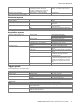
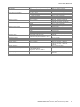
Protocol and logic
Bus trigger and decode number of bus signals 1
bus types
R&S
®
RTH-K1 option SPI, I
2
C
R&S
®
RTH-K2 option UART
display types decoded bus, logical signal, event table
position and size size and position on screen selectable
data format of decoded bus hex, decimal, binary
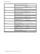
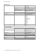
Data logger
Number of simultaneous logging channels 4
Sources R&S
®
RTH1004
oscilloscope mode up to 4 waveform measurements
digital voltmeter mode up to 4 digital voltmeter measurements
R&S
®
RTH1002
oscilloscope mode up to 4 waveform measurements
multimeter mode multimeter measurement
Timebase range selectable between 5 s/div and 4 days/div
Measurement speed 1/2/5 measurements/s
Memory depth 2 Msample per logging channel
Slot memory internal memory for up to 10 sets of data
logger results; slots results can be reset,
loaded and exported.
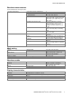
Digital voltmeter (DVM)
Sources R&S
®
RTH1004 CH1, CH2, CH3, CH4
Measurements voltage DC, AC, AC+DC
with indication of max., min. and average
Number of active measurements 4
Maximum resolution 999 counts, 3 digits
Digital multimeter (DMM)
Sources R&S
®
RTH1002 multimeter, 4 mm banana inputs, fully
isolated from scope inputs, interfaces and
ground
Measurements voltage DC, AC, AC+DC
current with current clamp or shunt
resistance
continuity test
diode test
temperature resistance measurement with PT100 or
PT500 platinum sensors
(recommended accessory R&S
®
HZ812
PT100 temperature probe)
frequency
capacitance
Number of active measurements 1
Maximum resolution 10000 counts, 4 digits
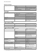
Input impedance
(voltage DC, AC, AC+DC)
1 V, 10 V 11.11 MΩ (nom.)
100 V 10.10 MΩ (nom.)
1000 V 10.01 MΩ (nom.)
Input capacitance < 100 pF
Common mode rejection ratio (CMRR) DC and 50 Hz/60 Hz ± 0.1 % > 100 dB (meas.)
Normal mode rejection ratio (NMRR) 50 Hz/60 Hz ± 0.1 % > 60 dB (meas.)
Maximum input voltage CAT III 1000 V (RMS), 1414 V (peak),
CAT IV 600 V (RMS), 849 V (peak),
derates at 20 dB/decade above 50 kHz
(see figure “Input rating: Maximum signal
voltage at meter input” on page 13)
Specified accuracy temperature range rated accuracy applies after 1 h
stabilization
+23 °C ± 5 °C
Temperature coefficient from 0 °C to +18 °C or +28 °C to +50 °C 0.1 × specified accuracy/°C