
User manual

Waveform Setup
R&S
®
RTB2000
38User Manual 1333.1611.02 ─ 06
4.3 Vertical Setup
The controls and parameters of the vertical system adjust the vertical scale and posi-
tion of the waveform, and the waveform display. The probe settings also belong to the
vertical setup.
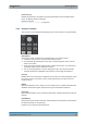
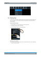
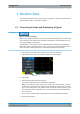
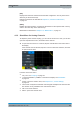
The channel labels at the bottom of the display show the basic vertical settings: vertical
scale (for example, channel 3 in the figure below: 500 mV/div), coupling (AC), probe
attenuation (10:1), and bandwidth (if limited). Clipping of a waveform is indicated by
orange arrows. The label of the selected channel has a brighter colored line on the top.
Figure 4-1: Channel labels. Channel 3 is selected. Channel 1 waveform is clipped.
There are several ways to adjust vertical settings:
●
Use the controls in the Vertical functional block of the front panel to select the
channel, to scale the waveform, and to set the offset.
●
Drag one finger vertically on the screen to change the offset of the selected chan-
nel waveform.
●
Spread or pinch two fingers in vertical direction to change the vertical scale of the
selected waveform.
●
Use the short menu to adjust coupling and the probe.
●
Use the comprehensive menu to adjust all vertical settings.
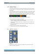
4.3.1 VERTICAL Controls
[Ch <n>]
For each analog channel, a channel key is available. The key is illuminated in the
channel color, if the channel is on.
Vertical Setup