
User manual

27
Instrument Functions
❙ Power:
Minimum modulation at the output corresponds to 0W
and maximum modulation corresponds to the maximum
current and voltage measuring ranges.
❙ Limit:
The limit module is connected to the analog output. The
output modulation is represented as a percentage %.
–100% corresponds to minimum modulation at the
output (≙ –5V) and +100% corresponds to maximum
modulation (≙ +5V). The limit value (LIM1 to LIM6) is
selected using softkey LIMIT NO and the rotary control
knob.
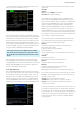
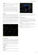
Example:
A 230 V DUT (for example, a desk lamp) is connected.
A crest factor of 3 and a measuring range of 300 V have
been selected, that is, the maximum measuring range is
300 V * 3 = 900 V. The 230 V of the DUT referenced to the
maximum measuring a range of 900 V and the maximum
deection of the ANALOG OUT of +5 V yields: (230 V / 900
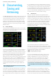
V) * 5 V = 1.278 V. If an oscilloscope is now connected
to ANALOG OUT on the back panel of the device and
ANALOG OUT is activated by way of the EXT menu, the
oscilloscope shows a sine curve on the screen with 1.278
VRMS or 3.6 Vpp (see Fig. 6.33).
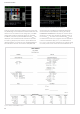
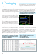
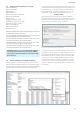
6.11.3 Digital IN
The DIGITAL IN can be activated (ON) or deactivated (OFF)
in the EXT menu by selecting softkey menu DIGITAL IN
and softkey ACTIVATE. In addition, the DIN function in the
cell conguration can be used to display the measured
value of the digital input signal on the screen. The differ-
ent modes can be selected using softkey MODE and the
rotary control knob:
❙ Frequency:
The power analyzer measures the frequency at the
DIGITAL IN.
❙ PWM:
The power analyzer measures the relationship between
High and Low.
❙ State:
The power analyzer measures the High and Low levels.
Fig. 6.33: Analog Out example
The softkey INVERT is used to invert the signal applied at
DIGITAL IN. This makes sense in STATE mode, for ex-
ample.
6.11.4 Digital OUT
The DIGITAL OUT can be activated (ON) or deactivated
(OFF) in the EXT menu by selecting softkey menu DIGITAL
OUT and softkey ACTIVATE. The external mode is selected
by using softkey MODE and the rotary control knob. The
following modes can be selected:
❙ Limit:
The limit module is connected to the digital output. The
High level at the output corresponds to logical True and
the Low level corresponds to False.
❙ FPLL:
The output is controlled by an FPGA and always outputs
the frequency of the selected source.
Fig. 6.34: DIGITAL IN menu.