
Datasheet

16
Instrument Functions
6 Instrument
Functions
6.1 Measurement Parameters
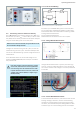
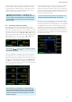
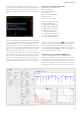
In NUMERIC mode, the instrument screen provides an
overview of the measurement values. The numeric values
displayed on the instrument screen are instantaneous val-
Fig. 6.1: R&S®HMC8015 readout display.
ues that are constantly updated. If an instrument function
is grayed out in the menu, the purchase of an option/up-
grade voucher is required in order to unlock this feature. If
the softkey of the grayed-out function is pressed, then an
info box appears on the screen with the required option/
upgrade voucher (see Chapter 3).
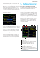
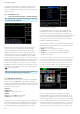
6.2 Display Modes (VIEW Menu)
The R&S®HMC8015 power analyzer includes ve differ-
ent display modes for the display of measurement results;
these can be enabled by activating options/upgrade
vouchers. The display modes can be selected using the
VIEW menu. The following display modes are available:
❙ Numeric mode: (default display)
Numeric display, toggles between six and ten
measurement parameters presented as cells with four
different conguration pages; this provides a quick
overview of the individual, congurable measurement
value cells.
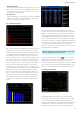
❙ Harmonics mode:
Bar graph of the rst 50 harmonics; this represents the
density of voltage / current as a percentage, absolute
value or as a list. HARMONICS mode is only available in
conjunction with the HOC151 option or the HVC151
upgrade voucher.
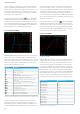
❙ Waveform mode:
Displays the waveform (for one cycle of voltage, current
or power data). WAVEFORM mode is only available in
conjunction with the HOC151 option or the HVC151
upgrade voucher.
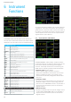
Fig. 6.3: VIEW menu.
Fig. 6.2: Option / upgrade voucher info box.
R&S®HMC8015 base unit
P Active power (W)
S Apparent power (VA)
Q Reactive power (var)
LAMBDA Power factor lambda (λ)
PHI Phase shift (φ)
FU Frequency value for the voltage (Hz)
FI Frequency value for the current (Hz)
FPLL Frequency and phase locked loop recording frequency (Hz)
URMS True root mean square (RMS) voltage (U
RMS
)
UAVG Average voltage
IRMS True root mean square (RMS) current (I
RMS
)
IAVG Average current
UTHD Total harmonic distortion U
ITHD Total harmonic distortion I
Wh+ Positive watt hours
Wh– Negative watt hours
Wh Sum of positive and negative watt hours
Ah+ Positive ampere hours
Ah– Negative ampere hours
Ah Sum of positive and negative ampere hours
R&S®HMC8015 base unit + HOC151 option /HVC151 voucher
UPPeak Maximum voltage (U
+pk
)
UMPeak Minimum voltage (U
–pk
)
IPPeak Maximum current (I
+pk
)
IMPeak Minimum current (I
–pk
)
PPPeak Maximum power (P
+pk
)
PMPeak Minimum power (P
–pk
)
R&S®HMC8015 base unit + HOC152 option /HVC152 voucher
DIN Digital input value (digital IN)
AIN Analog input value (analog IN)
Limit N Limit display
Table 6.1: Overview of measurement functions