
Datasheet

26
Instrument Functions
This setting has no effect on the internal acquisition of
measured values itself.
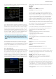
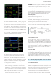
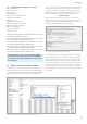
6.10 Limits
(only with HOC152 option / HVC152 voucher)
In the MEAS menu, the softkey menu LIMIT can be used
to dene up to six limit values. Once up to six limit val-
ues (LIM1 to LIM6) are selected in the cell conguration,
they can be activated (ON) or deactivated (OFF) using the
softkey ACTIVATE. The softkey SOURCE and the rotary
control knob can be used to select the measurement func-
tion for the source. Table 6.4 shows the possible measure-
ment functions. The softkeys HIGH and LOW are used to
dene maximum and minimum limit values. Similar to the
measuring range modulation, a bar is used to display the
limit values. This two-part bar indicates the modulation of
the limit from –100% (minimum modulation) to +100%
(maximum modulation). It is also possible to link the limit
function with the ANALOG OUT or DIGITAL OUT (EXT
menu). See Section 6.11.
Fig. 6.30: LIMIT menu.
Function Description
P Active power (W)
S Apparent power (VA)
Q Reactive power (var)
LAMBDA Power factor lambda (λ)
PHI Phase shift (φ)
FU Frequency value for the voltage (Hz)
FI Frequency value for the current (Hz)
FPLL
Frequency and phase locked loop recording fre-
quency (Hz)
URMS True root mean square (RMS) voltage (U
RMS
)
UAVG Average voltage
IRMS True root mean square (RMS) current (I
RMS
)
IAVG Average current
UTHD Total harmonic distortion U
ITHD Total harmonic distortion I
Table 6.4: Overview of LIMIT measurement functions
If the measuring instrument displays only dashes “-----” on the
display, either the limit function is not activated or an error oc-
curred (e.g. limit value LOW ≥ limit value HIGH).
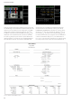
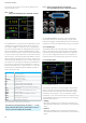
6.11 Analog / Digital Inputs and Outputs
(only with HOC152 option / HVC152 voucher)
On the R&S®HMC8015 rear panel, there are four BNC
connectors that can be used as analog or digital inputs
and outputs (Digital / Analog IN/OUT). The connectors are
available for limit values and Pass/Fail sorting, for example.
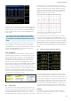
6.11.1 Analog IN
The ANALOG IN can be activated (ON) or deactivated
(OFF) in the EXT menu by selecting softkey menu ANA-
LOG IN and softkey ACTIVATE. In addition, the AIN func-
tion in the cell conguration can be used to display the
measured value of the analog input signal on the screen.
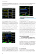
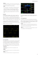
6.11.2 Analog OUT
The ANALOG OUT can be activated (ON) or deactivated
(OFF) in the EXT menu by selecting softkey menu ANA-
LOG OUT and softkey ACTIVATE. The minimum voltage
modulation of the output is -5V, the maximum voltage
modulation is +5V. The external mode is selected by using
softkey MODE and the rotary control knob. The following
modes can be selected:
❙ Voltage:
Minimum modulation at the output corresponds to 0V
and maximum modulation corresponds to the measuring
range.
❙ Current:
Minimum modulation at the output corresponds to 0V
and maximum modulation corresponds to the measuring
range.
Fig. 6.31: BNC connectors Digital / Analog IN/OUT.
Fig. 6.32: ANALOG OUT menu.