R&S®HMP Series Power Supplies User Manual (;ÜÒQ2) User Manual 1178.6833.
This manual describes the following models and options of the R&S®HMP Series: ● R&S®HMP2020 Two-Channel Power Supply (3629.6718.02) ● R&S®HMP2030 Three-Channel Power Supply (3629.6718.03) ● R&S®HMP4030 Three-Channel Power Supply (3629.6776.03) ● R&S®HMP4030 Four-Channel Power Supply (3629.6776.04) This manual describes firmware version FW V2.61 and later for the instruments of the of the R&S®HMP Series. © 2018 Rohde & Schwarz GmbH & Co. KG Mühldorfstr.
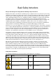
Basic Safety Instructions Always read through and comply with the following safety instructions! All plants and locations of the Rohde & Schwarz group of companies make every effort to keep the safety standards of our products up to date and to offer our customers the highest possible degree of safety. Our products and the auxiliary equipment they require are designed, built and tested in accordance with the safety standards that apply in each case.
Basic Safety Instructions Symbol Meaning Symbol Meaning Caution ! Hot surface Alternating current (AC) Protective conductor terminal To identify any terminal which is intended for connection to an external conductor for protection against electric shock in case of a fault, or the terminal of a protective earth Direct/alternating current (DC/AC) Earth (Ground) Class II Equipment to identify equipment meeting the safety requirements specified for Class II equipment (device protected by double or rei
Basic Safety Instructions Operating states and operating positions The product may be operated only under the operating conditions and in the positions specified by the manufacturer, without the product's ventilation being obstructed. If the manufacturer's specifications are not observed, this can result in electric shock, fire and/or serious personal injury or death. Applicable local or national safety regulations and rules for the prevention of accidents must be observed in all work performed. 1.
Basic Safety Instructions 6. The product may be operated only from TN/TT supply networks fuse-protected with max. 16 A (higher fuse only after consulting with the Rohde & Schwarz group of companies). 7. Do not insert the plug into sockets that are dusty or dirty. Insert the plug firmly and all the way into the socket provided for this purpose. Otherwise, sparks that result in fire and/or injuries may occur. 8.
Basic Safety Instructions 2. Before you move or transport the product, read and observe the section titled "Transport". 3. As with all industrially manufactured goods, the use of substances that induce an allergic reaction (allergens) such as nickel cannot be generally excluded.
Basic Safety Instructions 2. Adjustments, replacement of parts, maintenance and repair may be performed only by electrical experts authorized by Rohde & Schwarz. Only original parts may be used for replacing parts relevant to safety (e.g. power switches, power transformers, fuses). A safety test must always be performed after parts relevant to safety have been replaced (visual inspection, protective conductor test, insulation resistance measurement, leakage current measurement, functional test).
Instrucciones de seguridad elementales 3. If you use the product in a vehicle, it is the sole responsibility of the driver to drive the vehicle safely and properly. The manufacturer assumes no responsibility for accidents or collisions. Never use the product in a moving vehicle if doing so could distract the driver of the vehicle. Adequately secure the product in the vehicle to prevent injuries or other damage in the event of an accident. Waste disposal/Environmental protection 1.
Instrucciones de seguridad elementales Además queda en la responsabilidad del usuario utilizar el producto en la forma debida. Este producto está destinado exclusivamente al uso en la industria y el laboratorio o, si ha sido expresamente autorizado, para aplicaciones de campo y de ninguna manera deberá ser utilizado de modo que alguna persona/cosa pueda sufrir daño.
Instrucciones de seguridad elementales Símbolo Significado Símbolo Significado Conexión a tierra El aparato está protegido en su totalidad por un aislamiento doble (reforzado) Conexión a masa Distintivo de la UE para baterías y acumuladores Más información en la sección "Eliminación/protección del medio ambiente", punto 1.
Instrucciones de seguridad elementales Estados operativos y posiciones de funcionamiento El producto solamente debe ser utilizado según lo indicado por el fabricante respecto a los estados operativos y posiciones de funcionamiento sin que se obstruya la ventilación. Si no se siguen las indicaciones del fabricante, pueden producirse choques eléctricos, incendios y/o lesiones graves con posible consecuencia de muerte.
Instrucciones de seguridad elementales integran productos sin interruptor en bastidores o instalaciones, se deberá colocar el interruptor en el nivel de la instalación. 5. No utilice nunca el producto si está dañado el cable de conexión a red. Compruebe regularmente el correcto estado de los cables de conexión a red. Asegúrese, mediante las medidas de protección y de instalación adecuadas, de que el cable de conexión a red no pueda ser dañado o de que nadie pueda ser dañado por él, p. ej.
Instrucciones de seguridad elementales 17. No utilice el producto en condiciones en las que pueda producirse o ya se hayan producido condensaciones sobre el producto o en el interior de éste, como p. ej. al desplazarlo de un lugar frío a otro caliente. La entrada de agua aumenta el riesgo de choque eléctrico. 18. Antes de la limpieza, desconecte por completo el producto de la alimentación de tensión (p. ej. red de alimentación o batería).
Instrucciones de seguridad elementales pueden causar perturbaciones radioeléctricas en entornos residenciales debido a posibles perturbaciones guiadas o radiadas. En este caso, se le podrá solicitar al operador que tome las medidas adecuadas para eliminar estas perturbaciones. Aparato de clase B: Aparato adecuado para su uso en entornos residenciales, así como en aquellos conectados directamente a una red de distribución de baja tensión que suministra corriente a edificios residenciales.
Instrucciones de seguridad elementales 8. En caso de devolver baterías de litio a las filiales de Rohde & Schwarz, debe cumplirse las normativas sobre los modos de transporte (IATA-DGR, código IMDG, ADR, RID). Transporte 1. El producto puede tener un peso elevado. Por eso es necesario desplazarlo o transportarlo con precaución y, si es necesario, usando un sistema de elevación adecuado (p. ej. una carretilla elevadora), a fin de evitar lesiones en la espalda u otros daños personales. 2.
Customer Support Technical support – where and when you need it For quick, expert help with any Rohde & Schwarz equipment, contact one of our Customer Support Centers. A team of highly qualified engineers provides telephone support and will work with you to find a solution to your query on any aspect of the operation, programming or applications of Rohde & Schwarz equipment.
R&S®HMP Series Contents Contents 1 Preface.................................................................................................... 7 1.1 Key Features..................................................................................................................7 1.2 Documentation Overview............................................................................................. 7 1.2.1 Getting Started Manual..............................................................................
R&S®HMP Series Contents 4 Instrument Functions.......................................................................... 31 4.1 About the Output Modes of the R&S HMP................................................................ 31 4.2 Basic Functions.......................................................................................................... 33 4.2.1 Setting the Voltage, Current and Fuse Parameters and Activating an Output..............33 4.2.2 Using the Tracking Function............
R&S®HMP Series Contents 8.1 Common Setting Commands.....................................................................................57 8.2 System Setting Commands........................................................................................60 8.3 Configuration Commands.......................................................................................... 62 8.3.1 Channel Selection Commands......................................................................................62 8.3.
R&S®HMP Series User Manual 1178.6833.
R&S®HMP Series Preface Documentation Overview 1 Preface 1.1 Key Features The R&S HMP Series power supplies sets standards in performance and usability. Outstanding key features are: ● High output power within a minimum space, high efficiency and low residual ripple. ● High programming and readback resolution for applications with the highest demands. ● Realtime voltage, current and power values. ● EasyArb function for programming voltage and current processes directly on the instrument.
R&S®HMP Series Preface For Your Safety 1.2.3 Basic Safety Instructions Contains safety instructions, operating conditions and further important information. The printed document is delivered with the instrument. 1.2.4 Brochure and Specifications The brochure provides an overview of the instrument and deals with the specific characteristics. It contains the technical specifications of the R&S HMP, and provides ordering information for the base units, available options and accessories. See www.
R&S®HMP Series Preface For Your Safety ● Throughout the documentation, safety instructions are provided when you need to take care during setup or operation. Always read the safety instructions carefully. Make sure to comply fully with them. Do not take risks and do not underestimate the potential danger of small details such as a damaged power cable. User Manual 1178.6833.
R&S®HMP Series Welcome to the R&S HMP Series 2 Welcome to the R&S HMP Series The programmable 2-, 3- or 4-channel high-performance power supplies are based on a classical transformer concept with high efficiency electronic pre-regulators and secondary linear regulators. This concept allows the instrument to achieve the high output power within a minimum space, high efficiency and lowest residual ripple.
R&S®HMP Series Getting Started Preparing for Use 3 Getting Started This section contains the information you have received as a printed book together with your instrument. The information is provided again to enable you to search throughout the complete description. 3.1 Preparing for Use 3.1.1 Putting into Operation This section describes the basic steps to be taken when setting up the R&S HMP for the first time. 3.1.1.
R&S®HMP Series Getting Started Preparing for Use Risk of injury due to disregarding safety information Observe the information on appropriate operating conditions provided in the data sheet to prevent personal injury or damage to the instrument. Read and observe the basic safety instructions provided with the instrument, in addition to the safety instructions in the following sections. In particular: ● Do not open the instrument casing.
R&S®HMP Series Getting Started Preparing for Use Risk of instrument damage during operation An unsuitable operating site or test setup can damage the instrument and connected devices. Ensure the following operating conditions before you switch on the instrument: ● Make sure that the nominal voltage setting on the product matches the nominal voltage of the AC supply network. If you have a different line voltage, it can be necessary that you have to change the power fuse of the product.
R&S®HMP Series Getting Started Preparing for Use ● The fuse holder shows damage ● The instrument is no longer working – After an extended period of storage under unfavorable conditions (e.g. outdoors or in damp rooms) – After rough handling during transport (e.g. packaging that does not meet the minimum requirements by post office, railway or forwarding agency) EMI impact on measurement results Electromagnetic interference (EMI) can affect the measurement results.
R&S®HMP Series Getting Started Preparing for Use 3.1.1.3 Delivery List The instrument comes with the following components: 3.1.1.
R&S®HMP Series Getting Started Preparing for Use Risk of injury when stacking instruments A stack of instruments can tilt over and cause injury if not stacked correctly. Furthermore, the instruments at the bottom of the stack can be damaged due to the load imposed by the instruments on top. Observe the following instructions when stacking instruments: ● Never stack more than three instruments. If you need to stack more than three instruments, install them in a rack.
R&S®HMP Series Getting Started Preparing for Use Risk of instrument damage due to insufficient airflow in a rack If the instrument is run with insufficient airflow for a longer period, the instrument overheats, which can disturb the operation or turn off the R&S HMP. Make sure that all fan openings are unobstructed, that the airflow perforations are unimpeded, and that the minimum distance from the wall is 10 cm. 3.1.1.
R&S®HMP Series Getting Started Preparing for Use Risk of electric shock The fuses are part of the main power supply. Therefore, handling the fuses while power is on can lead to electric shock. Before opening the fuse holder, make sure that the instrument is switched off and disconnected from all power sources. Always use fuses supplied by Rohde & Schwarz as spare parts, or fuses of the same type and rating.
R&S®HMP Series Getting Started Preparing for Use 2. Turn on the instrument with the main Power key in the upper left corner at the front panel. The R&S HMP starts up using the same operating mode that was in use at the time the unit was last turned off. The instrument turns off the output signals at the beginning of operation. This function prevents a connected load from being supplied unintentionally at startup.
R&S®HMP Series Getting Started Preparing for Use Risk of network connection failure Network cables and cable connectors of poor quality, or failures in the autonegotiation process, can cause network connection failures. If the network connection to the instrument fails, check the network infrastructure and contact your network administrator. To set up a network (LAN) connection ► Connect the instrument to the network or a single PC.
R&S®HMP Series Getting Started Instrument Tour Switching to remote control When you turn on the instrument, it always starts in manual operation state ("local" mode) to be operated via the front panel. 1. To establish communication via remote control, send a SCPI command. The R&S HMP switches to remote control mode automatically. The Remote key illuminates. The remote control mode disables all front panel keys on the instrument. 2. To return to local mode, press the Remote key.
R&S®HMP Series Getting Started Instrument Tour Figure 3-1: Front view of the R&S HMP2030 1 2 3 4 5 6 7 8 9 10 11 12 13 14 15 16 = = = = = = = = = = = = = = = = Power key: Turning the instrument on and off Display (LCD): Parameter display Arrow keys and Rotary knob: Navigating on the display, setting and confirming the parameters Ch1, Ch2, Ch3 keys: Selecting Channels Output key: Turning on or off the selected channels Voltage key: Setting the output voltage Track key: Activating the tracking function St
R&S®HMP Series Getting Started Instrument Tour Figure 3-2: Front view of the R&S HMP4040 1 2 3 4 5 6 7 8 9 10 11 12 13 14 15 16 17 18 = = = = = = = = = = = = = = = = = = Power key: Turning the instrument on and off Display (LCD): Parameter display Arrow keys and Rotary knob: Navigating on the display, setting and confirming the parameters Ch1, Ch2, Ch3, Ch4 keys: Selecting Channels Output key: Turning on or off the selected channels Keypad keys: Setting the nominal values Voltage key: Setting the output
R&S®HMP Series Getting Started Instrument Tour Figure 3-3: Rear view of the HMP20x0 series 17 18 19 20 = = = = Interface: Ethernet / USB dual interface R&S HO732 (default for all instruments of the R&S HMP series) Output connector: Rear panel outputs for integration into rack systems (2 to 3 channels) Voltage selector: Selecting the line voltage 115 V or 230 V Power supply connector: IEC socket and fuse holder 3.2.
R&S®HMP Series Getting Started Trying Out the Instrument Risk of interference by electrostatic discharge When the front and rear connectors are connected simultaneously, interferences due to electrostatic discharge can occur. To prevent interferences, leave the output sockets at the front disconnected, when using the rear panel outputs. 3.3 Trying Out the Instrument This chapter describes the first steps with the R&S HMP. It shows a simple configuration for providing the power at the output.
R&S®HMP Series Getting Started Trying Out the Instrument The Voltage key and the arrow keys are illuminated, indicating that they are active. 2. Press the channel key, e.g. Ch1. Activates the voltage setting. The Ch1 key illuminates blue. 3. Set the output voltage value by turning the rotary knob. The R&S HMP applies the setting immediately. 4. To terminate the setting, press the Voltage key. The Ch1 key illuminates green again.
R&S®HMP Series Getting Started Instrument Control 2. Press the Output key. The Output key turns on the outputs of all activated channels and supplies the connected loads. Saving instrument settings You can save up to 10 measurement configurations in the memory locations provided by the instrument. 1. Press the Store key. The "Store Settings" dialog opens. 2. Use the rotary knob to select the memory location. 3. Confirm with the rotary knob. 4. Return with the Store key. The R&S HMP saves the settings.
R&S®HMP Series Getting Started Instrument Control "Remote Control", on page 30 provides a brief overview of the interfaces provided for remote control. See Chapter 3.1.2, "Setting Up a Network (LAN) Connection", on page 19 and Chapter 7, "Network Operation and Remote Control", on page 53. 3.4.2 Means of Manual Interaction To configure the R&S HMP manually, use the front panel controls, see Chapter 3.2, "Instrument Tour", on page 21.
R&S®HMP Series Getting Started Instrument Control The navigation controls include a rotary knob and arrow keys. They allow you to navigate within a setting, menus or dialogs. ● Rotary knob The rotary knob has several functions: ● – Moves the selection, e.g.
R&S®HMP Series Getting Started Instrument Control 3.4.3 Remote Control In addition to operating the R&S HMP directly on the instrument, it is also possible to operate and control it from a remote PC.
R&S®HMP Series Instrument Functions About the Output Modes of the R&S HMP 4 Instrument Functions This section explains the operating modes, and the operating procedures and advanced functions of the R&S HMP. The display and the controls on the front of the R&S HMP form the user interface for controlling the instrument manually. The display shows the current settings, and leads you to the dialogs of the corresponding functions. 4.
R&S®HMP Series Instrument Functions About the Output Modes of the R&S HMP Setting Imax, the current limit The current limit determines the maximum value Imax of the output current. Limiting the output current prevents damage to a connected DUT in case of failure, i.e. schort circuit. Always set Imax before you take a DUT into operation. The maximum current Imax corresponds to the setting with the Current key, see "Setting the current limit" on page 26.
R&S®HMP Series Instrument Functions Basic Functions 4.2 Basic Functions 4.2.1 Setting the Voltage, Current and Fuse Parameters and Activating an Output Select the channel Selects one or more channels for setting the parameters. See "Selecting the channels" on page 25. Remote command: INSTrument[:SELect] on page 63 INSTrument:NSELect on page 63 Set the voltage Sets the voltage for selected channel. See "Selecting the output voltage" on page 25.
R&S®HMP Series Instrument Functions Basic Functions Devices with keypad (R&S HMP 40xx series) allow you to set the same value for all linked channels in addition to the amount change. To change the voltage or current values by the same amount 1. Press the Track key. 2. Press the Voltage key. 3. Press the channel keys of the channels you want to adjust simultaneously.
R&S®HMP Series Instrument Functions Advanced Functions Figure 4-3: Setting the same voltage for two channels with the tracking function 4. Set the value using the keypad. 5. Confirm with Enter. 6. Press the Current key. 7. Repeat steps 3 to 5 to adjust the current limit values. During tracking, the R&S HMP power supply retains the previously selected voltage and current difference between the channels until a channel has reached the minimum or maximum value of the voltage or current.
R&S®HMP Series Instrument Functions Advanced Functions Fuse Linking The fuse linking function allows you to interlink channels with their electronic fuses logically. Access: 1. Press the Menu key. 2. Select "Fuse Linking" by pressing the rotary knob or the right arrow key. 3. Select the channel by turning the rotary knob. 4. Select the channel on the right to link with the selected channel. Figure 4-4: Fuse linking (example R&S HMP4040) 5. Press the Menu key to return to the display screen.
R&S®HMP Series Instrument Functions Advanced Functions When the current for a channel exceeds the value Imax and the electronic fuse trips, all channels interlinked with this channel are turned off also. The Output key remains active. See "Activate the fuse" on page 33 on how to activate a fuse in general. At any time, you can reactivate the channels via the corresponding keys. If any excess current remains, the R&S HMP immediately turns off the output again.
R&S®HMP Series Instrument Functions Advanced Functions When OVP is activated and the output voltage exceeds the set OVP value, the R&S HMP indicates a flashing "OVP" in the corresponding channel and turns off the output of this channel. Figure 4-6: Overvoltage protection (example R&S HMP2030) The remote commands for setting the overvoltage parameters are described in Chapter 8.3.7, "Overvoltage Protection Setting Commands", on page 72. OVP Level...........................................................
R&S®HMP Series Instrument Functions Advanced Functions HMExplorer software, available for download on the Internet, see www.rohdeschwarz.com/software/hmp/. The EasyArb editor of the R&S HMExplorer software enables you to create any point of a waveform conveniently, by adding or deleting individual points. Figure 4-7: Arbitrary-Editor example (excerpt) HMExplorer Software To activate an arbitrary waveform, transfer the waveforms to the output channels of the R&S HMP, and activate the output.
R&S®HMP Series Instrument Functions Advanced Functions Figure 4-8: Output arbitrary example on an oscilloscope The following description creates a waveform via the control panel, transmits the waveform to the channels and starts signal generation. Creating and saving a waveform Access: 1. Press the Menu key. 2. Select "Arbitrary" by pressing the rotary knob or the right arrow key. 3. In the arbitrary menu, select "Edit Waveform".
R&S®HMP Series Instrument Functions Advanced Functions 7. When completed, return with the left arrow key. 8. Select "Save Waveform" to save the data in the internal memory. Each channel provides three internal memories for saving waveforms. 9. Select the memory location. 10. Confirm your selection by pressing the rotary knob. The R&S HMP confirms with a message when the waveform data is saved. 11. Select the corresponding parameter, e.g. "Voltage" by pressing the rotary knob or the down arrow key.
R&S®HMP Series Instrument Functions Advanced Functions └ Time................................................................................................................ 42 └ Voltage............................................................................................................42 └ Current............................................................................................................ 42 └ Repetitions...............................................................................
R&S®HMP Series Instrument Functions General Instrument Functions Remote command: ARBitrary:DATA on page 77 Repetitions ← Edit Waveform Sets the repetition rate for the current index entry. Remote command: ARBitrary:DATA on page 77 Clear Waveform Deletes any previously made settings. Remote command: ARBitrary:Clear on page 76 Save Waveform Saves up to 3 settings (waveforms) Remote command: ARBitrary:SAVE on page 78 Recall Waveform Recalls a previously saved waveform.
R&S®HMP Series Instrument Functions General Instrument Functions Select Interface Selects the interface used to establish a remote connection. Options depend on the installed remote control interface. HO720 USB/RS-232 Provides parameters for the dual USB/RS-232 remote control interface. "Baud Rate" Sets the data transmission rate in seconds for the serial remote control interface. "Number of Stop Bits" Sets the number of stop bits for the serial remote control interface.
R&S®HMP Series Instrument Functions General Instrument Functions Key Brightness (R&S HMP2020/2030)......................................................................... 45 Key Fallback Time.........................................................................................................45 Display Contrast............................................................................................................45 Display and Key Brightness (R&S HMP4030/4040)......................................
R&S®HMP Series Instrument Functions General Instrument Functions Figure 4-11: Fig. 5.9: Beeper (R&S HMP2030) "On" Beeps every time the key is pressed. "Off" Does not beep on any occasion. "Critical Events Only" Beeps when an error occurs. Remote command: SYSTem:BEEPer[:IMMediate] on page 60 4.4.4 Information Access: 1. Press the Menu key. 2. Select "Information" by pressing the rotary knob or the right arrow key.
R&S®HMP Series Application Examples Operating in Parallel and Serial Mode 5 Application Examples 5.1 Compensating Voltage Drops on the Supply Lines Figure 5-1: Compensating the voltage drops in diagram The two SENSE lines allow you to compensate voltage drops on the supply lines to the load so that the selected voltage is applied to the load. Use two separate measuring lines to connect the load to the two external black safety sockets of the respective channel (see Figure 5-1). 5.
R&S®HMP Series Application Examples Operating in Parallel and Serial Mode 5.2.1 Serial Mode Risk of electric shock due to exceeding low voltage protection For the series connection of all output voltages, it is possible to exceed the low voltage protection. In this case, any contact with live components is life-threatening. It is assumed that only qualified and trained personnel operate the power supplies and the connected loads. The following interconnection adds the individual output voltages.
R&S®HMP Series Application Examples Multi-Quadrant Operation Figure 5-3: Example of a parallel connection Generally, the channel with the highest output voltage provides the highest current. When this channel reaches the current limit, the channel connected in parallel supplies the remaining current. Note, that the voltages in the individual channels differ slightly due to tolerances. By increasing the voltage slightly, you can distribute the load more evenly.
R&S®HMP Series Application Examples Multi-Quadrant Operation reach a range between -32 V and +32 V. It does not refer to a negative display on the screen, but rather to a connection with an identical voltage range. However, a negative current (current sink) is not possible. Figure 5-5: Example of a multi-quadrant connection User Manual 1178.6833.
R&S®HMP Series Maintenance Cleaning 6 Maintenance The instrument does not need periodic maintenance. Only the cleaning of the instrument is essential. Any adjustments, replacements of parts, maintenance and repair must be done only by authorized Rohde & Schwarz technical personnel. Original parts must be used for replacing parts relevant to safety (e.g. power switches, power transformers, fuses). After replacement of safety relevant parts, e.g.
R&S®HMP Series Maintenance Storing and Packing Instrument damage caused by cleaning agents Cleaning agents contain substances such as solvents (thinners, acetone, etc.), acids, bases, or other substances. Solvents can damage the front panel labeling, plastic parts, or screens, for example. Never use cleaning agents to clean the outside of the instrument. Use a soft, dry, lintfree dust cloth instead.
R&S®HMP Series Network Operation and Remote Control Remote Control Interfaces 7 Network Operation and Remote Control This chapter provides basic information on operating an instrument via remote control. For additional information on remote control basics, and the SCPI command structure, see Chapter A, "Additional Basics on Remote Control", on page 81. 7.
R&S®HMP Series Network Operation and Remote Control Remote Control Interfaces The resource string is required to establish a communication session between the controller and the instrument in a LAN. The resource string is a unique identifier, composed of the specific IP address of the instrument and some network and specific keywords. IP address To set up the connection, you require the IP address of the instrument.
R&S®HMP Series Network Operation and Remote Control Remote Control Interfaces If you use the virtual COM port, you have to install the "HO720 / HO730 Virtual COM Port" driver, available for download on the product page at www.rohde-schwarz.com/ driver/hmp. Activate the virtual COM port (VCP) in the PC device explorer. 7.1.3 RS-232 Interface If you use the classic RS-232 interface (R&S HO720 RS232 part), you do not need any driver.
R&S®HMP Series Network Operation and Remote Control Remote Control Interfaces 7.1.4 GPIB Interface (IEC/IEEE Bus Interface) To control the instrument via the GPIB bus (R&S HO740 GPIB Interface IEEE-488), the instrument and the controller must be connected by a GPIB bus cable. A GPIB bus card, the card drivers and the program libraries for the programming language used must be provided in the controller. The controller addresses the instrument within the GPIB bus channel.
R&S®HMP Series Remote Control Commands Common Setting Commands 8 Remote Control Commands This chapter provides the description of all remote commands available for the R&S HMP series. The commands are sorted according to the menu structure of the instrument. A list of commands in alphabetical order is given in the "List of Commands" at the end of this documentation. 8.1 Common Setting Commands Common commands are described in the IEEE 488.2 (IEC 625-2) standard.
R&S®HMP Series Remote Control Commands Common Setting Commands *ESR? Event status read Returns the contents of the event status register in decimal form and subsequently sets the register to zero. Return values: Range: Usage: Query only 0 to 255 *IDN? Identification Returns the instrument identification.
R&S®HMP Series Remote Control Commands Common Setting Commands Parameters: Contents of the service request enable register in decimal form. Bit 6 (MSS mask bit) is always 0. Range: 0 to 255 *STB? Status byte query Reads the contents of the status byte in decimal form. Usage: Query only *TST? Self-test query Initiates self-tests of the instrument and returns an error code Return values: integer > 0 (in decimal format) An error occurred. 0 No errors occurred.
R&S®HMP Series Remote Control Commands System Setting Commands Loads the instrument settings from an internal memory identified by the specified number. The instrument settings can be stored to this memory using the command *SAV with the associated number. Manual operation: See "Recall" on page 35 8.2 System Setting Commands The SYSTem subsystem contains the commands for general functions, which do not affect signal generation directly. SYSTem:BEEPer[:IMMediate]..........................................
R&S®HMP Series Remote Control Commands System Setting Commands Usage: Query only SYSTem:LOCal Enables manual (front panel) control. The command switches from remote control to manual control, and is required, when you have locked manual control before, see SYSTem:RWLock on page 61. Example: SYST:LOC // returns from remote control to manual control Usage: Event SYSTem:MIX Enables remote control without locking manual control. You can control the instrument in both modes simultaneously (mixed mode).
R&S®HMP Series Remote Control Commands Configuration Commands Example: SYST:VERS? // queries the SCPI version // response: "1996" Usage: Query only 8.3 Configuration Commands 8.3.1 Channel Selection Commands The INSTrument:Select subsystem contains the commands for selecting the output channels. Each channel of the power supply is considered as separate "instrument", which is required by the SCPI standard. Therefore, the SCPI commands use the INSTRument node to select a channel.
R&S®HMP Series Remote Control Commands Configuration Commands INSTrument:NSELect Selects a channel by number. Parameters: {1 | 2 | 3 | 4} Example: See Example "Selecting a channel" on page 62. Manual operation: See "Select the channel" on page 33 INSTrument[:SELect] Selects the channel.
R&S®HMP Series Remote Control Commands Configuration Commands Example: Configuring the output voltage This example contains all commands to configure and query the output voltage. // ************************************************ // Set the voltage value // ************************************************ INST OUT1 VOLT 10 // selects a channel and sets the voltage VOLT MAX VOLT MIN // sets the voltage to maximum or minimum respectively VOLT? // queries the output voltage of a channel // response: "10.
R&S®HMP Series Remote Control Commands Configuration Commands Parameters: MINimum | MAXimum | UP | DOWN Range: 0.000 to 32.050 Increment: 0.001 Default unit: V Example: See Example "Configuring the output voltage" on page 64. Manual operation: See "Set the voltage" on page 33 [SOURce:]VOLTage[:LEVel]:STEP[:INCRement] Sets the voltage step size for the VOLT UP | VOLT DOWN command. Parameters: Range: 0.000 to 32.050 *RST: 1.
R&S®HMP Series Remote Control Commands Configuration Commands Example: Configuring the current limit This example contains all commands to configure and query the output voltage. // ************************************************ // Set the voltage value // ************************************************ INST OUT1 CURR 2 // selects a channel and sets the current CURR? // queries the current of he selected channel // response: 2.
R&S®HMP Series Remote Control Commands Configuration Commands Example: See Example "Configuring the current limit" on page 66. Manual operation: See "Set the current limit" on page 33 [SOURce:]CURRent[:LEVel]:STEP[:INCRement] Sets the current step size for the CURR UP | CURR DOWN command. Parameters: Range: 0.005 / 0.001 to 10.0100A *RST: 0.100 A Default unit: A Example: See Example "Configuring the current limit" on page 66.
R&S®HMP Series Remote Control Commands Configuration Commands 8.3.5 Output Setting Commands The OUTPut subsystem contains the commands for activating the output channels. Example: Activating the channels You can activate a selected channel and turn on or off the outputs either individually or all outputs simultaneously. This example lists all ways how you can activate and query the outputs.
R&S®HMP Series Remote Control Commands Configuration Commands Parameters: {OFF | ON | 0 | 1} *RST: 0 Example: See Example "Activating the channels" on page 68. Usage: Setting only OUTPut:SELect Activates the selected channel. Parameters: {OFF | ON | 0 | 1} *RST: 0 Example: See Example "Activating the channels" on page 68. Usage: Setting only OUTPut[:STATe] Activates the selected channel and turns on the output.
R&S®HMP Series Remote Control Commands Configuration Commands Example: Configuring fuses This example contains all commands to configure and query the fuse states and settings.
R&S®HMP Series Remote Control Commands Configuration Commands // response: 1 when the fuse is linked // response: 0 when the fuse is not linked // ************************************************ // Dissolve the link of the electronic fuses // ************************************************ INST OUT1 FUSE:LINK 2 FUSE:UNL 2 // links the fuse of channel 1 with channel2 // dissolves the fuse link // ************************************************ // Query a tripped fuse // *********************************
R&S®HMP Series Remote Control Commands Configuration Commands FUSE:TRIPped? Queries whether the fuse has tripped in the selected channel. Return values: {ON | OFF | 0 | 1} 1 Fuse is tripped. 0 Fuse is not tripped. Example: See Example "Configuring fuses " on page 70. Usage: Query only FUSE:UNLink Dissolves linked fuses. Parameters: {1 | 2 | 3 | 4} Example: See Example "Configuring fuses " on page 70.
R&S®HMP Series Remote Control Commands Configuration Commands Example: Configuring the overvoltage protection This example contains all commands to configure and query the protection of the output voltage.
R&S®HMP Series Remote Control Commands Configuration Commands VOLTage:PROTection[:LEVel]...........................................................................................74 VOLTage:PROTection:CLEar............................................................................................74 [SOURce:]VOLTage:PROTection:MODE............................................................................74 VOLTage:PROTection:TRIPped?.......................................................................
R&S®HMP Series Remote Control Commands Arbitrary Setting Commands Return values: {OFF | ON | 0 | 1} Example: See Example "Configuring the overvoltage protection" on page 73. Usage: Query only 8.4 Measurement Commands The MEASure subsystem provides commands to query the voltage and current values of a channel. MEASure[:SCALar]:CURRent[:DC]?.................................................................................. 75 MEASure[:SCALar]:VOLTage[:DC]........................................
R&S®HMP Series Remote Control Commands Arbitrary Setting Commands Example: Configuring an arbitrary sequence This programming example generates an arbitrary sequence for a selected channel. The sequence starts at 1 V and 1 A for 1 sec, and both values are incremented each second by 1. The generated arbitrary waveform is transferred to CH1. When activated, the R&S HMP provides the arbitrary waveform at the output of the selected channel, and repeats it 10 times.
R&S®HMP Series Remote Control Commands Arbitrary Setting Commands Parameters: 1|2|3|4 Example: See Example "Configuring an arbitrary sequence" on page 76. Usage: Setting only Manual operation: See "Clear Waveform" on page 43 ARBitrary:DATA Defines the arbitrary voltage, current and time value points for the selected channel. The dwell time between two arbitrary points is specified from 10 ms to 60 s. Parameters:
R&S®HMP Series Remote Control Commands Arbitrary Setting Commands ARBitrary:SAVE Saves the arbitrary waveform data in the internal memory. You can save up to three waveforms in the internal memory. Parameters: 1|2|3 Example: See Example "Configuring an arbitrary sequence" on page 76. Usage: Setting only Manual operation: See "Save Waveform" on page 43 ARBitrary:START Starts the arbitrary sequence in the selected channel.
R&S®HMP Series Remote Control Commands Status Reporting 8.6 Status Reporting 8.6.1 STATus:QUEStionable Registers The commands of the STATus:QUEStionable subsystem control the status reporting structures of the STATus:QUEStionable registers. See also: ● Chapter A.3.1, "Structure of a SCPI Status Register", on page 87 ● "STATus:QUEStionable Register" on page 89 STATus:QUEStionable:ENABle.........................................................................................
R&S®HMP Series Remote Control Commands Status Reporting STATus:QUEStionable:INSTrument:ISUMmary:CONDition? Returns the contents of the CONDition part of the status register to check the actual instrument states. Reading the CONDition registers does not delete the contents. Return values: Condition bits in decimal representation Range: Usage: User Manual 1178.6833.
R&S®HMP Series Additional Basics on Remote Control Messages and Command Structure Annex A Additional Basics on Remote Control A.1 Messages and Command Structure A.1.1 Messages Instrument messages are employed in the same way for all interfaces, if not indicated otherwise in the description. See also: ● Structure and syntax of the instrument messages: Chapter A.1.
R&S®HMP Series Additional Basics on Remote Control Messages and Command Structure are device-specific, however, their syntax follows SCPI rules as permitted by the standard. Instrument responses Instrument responses (response messages and service requests) are messages which the instrument sends to the controller after a query. They can contain measurement results, instrument settings and information on the instrument status.
R&S®HMP Series Additional Basics on Remote Control Messages and Command Structure Syntax for Device-Specific Commands For demonstration purposes only, assume the existence of the following commands for this section: ● MEASure:CURRent[:DC]? ● MEASure:VOLTage[:DC]? ● FUSE[:STATe] {ON | OFF | 0 | 1} ● FUSE[:STATe]? Long and short form The mnemonics feature a long form and a short form. The short form is marked by uppercase letters, the long form corresponds to the complete word.
R&S®HMP Series Additional Basics on Remote Control Messages and Command Structure Special characters Table A-2: Special characters | A vertical stroke in parameter definitions indicates alternative possibilities in the sense of "or". The effect of the command differs, depending on the used parameter.
R&S®HMP Series Additional Basics on Remote Control Messages and Command Structure ● MINimum and MAXimum denote the minimum and maximum value. Example: VOLT:PROT? MAX Returns the maximum numeric value. Boolean parameters Boolean parameters represent two states: ● On (logically true), is represented by "On" or the numeric value "1" ● Off (logically false), is represented by "Off" or the numeric value "0" The instrument returns the numerical value when queried.
R&S®HMP Series Additional Basics on Remote Control Status Reporting System A.2 Command Sequence and Synchronization A sequential command finishes the execution before the next command is starting. To make sure that commands are actually carried out in a certain order, each command must be sent in a separate command line. As a rule, send commands and queries in different program messages. A.2.
R&S®HMP Series Additional Basics on Remote Control Status Reporting System A.3.1 Structure of a SCPI Status Register Each standard SCPI register consists of 2 or 3 parts (Event, Condition and Enable register). Each part has a width of 16 bits and has different functions. The individual bits are independent of each other, i.e. each hardware status is assigned a bit number which is valid for all 2 or 3 parts. Bit 15 (the most significant bit) is set to zero for all parts.
R&S®HMP Series Additional Basics on Remote Control Status Reporting System Bits 11 to 13 are still "free" resp. unused (always return a "0"). Certain areas of the registers are not used. The SCPI standard defines only the "basic functions". Some devices offer an advanced functionality. Each channel of the power supply is considered as separate "instrument" (SCPI standard definition). Therefore, e.g.
R&S®HMP Series Additional Basics on Remote Control Status Reporting System STATus:QUEStionable Register This register contains information about different states which can occur. It can be read using the commands STATus:QUEStionable:CONDition? and STATus:QUEStionable[:EVENt]?. See also Figure A-1. Table A-5: Bits of the STATus:QUEStionable register Bit No. Meaning 0 Voltage This bit is set while the instrument is in constant current mode (CC). The voltage is regulated and the current is constant.
R&S®HMP Series Additional Basics on Remote Control Status Reporting System Figure A-2: Decimal representation of a bit pattern Error Queue Each error state in the instrument leads to an entry in the error queue. The entries of the error queue are detailed plain text error messages. You can look them up in the error log or via remote control using SYSTem:ERRor[:NEXT]?. Each call of SYSTem:ERRor[:NEXT]? provides one entry from the error queue.
R&S®HMP Series Hardware Interfaces GPIB B Hardware Interfaces This section covers hardware-related topics, like pin assignment of the IEC 625/ IEEE 488 interface. The remote control interfaces are described in details in Chapter 7.1, "Remote Control Interfaces", on page 53. All other interfaces and connectors are described briefly in Chapter 3.2, "Instrument Tour", on page 21 For specifications, refer to the data sheet. B.
R&S®HMP Series Hardware Interfaces RS-232 SRQ (Service Request): active LOW enables the connected device to send a service request to the controller. REN (Remote Enable): active LOW permits switchover to remote control. EOI (End or Identify): has two functions in connection with ATN: ● – ATN=HIGH active LOW marks the end of data transmission. – ATN=LOW active LOW triggers a parallel poll. Handshake bus with three lines: DAV (Data Valid): active LOW signals a valid data byte on the data bus.
R&S®HMP Series Hardware Interfaces RS-232 Pin Assignment Figure B-2: RS232 Pin Assignment 1 2 3 4 5 = = = = = 6 7 8 9 = = = = unused Tx data (data from power supply to external device) Rx data (data from external device to power supply) unused Ground (reference potential, connected with power supply (safety class II) and power cable to the grounding conductor unused CTS (Clear To Send) RTS (Request To Send) +5 V supply voltage for external devices (max.
R&S®HMP Series Glossary: List of the Often Used Terms and Abbreviations Glossary: List of the Often Used Terms and Abbreviations C CC: Constant current output mode Computer name: An unambiguous indication of the instrument a LAN that uses a DNS server. Synonym: Hostname See Serial number. CP: Constant voltage output mode D DHCP: Dynamic host configuration protocol E e.g.: For example G Glosssary: List of the often used terms and abbreviations H Hostname: Computer name I i.e.
R&S®HMP Series Glossary: List of the Often Used Terms and Abbreviations S Serial number: Unique instrument identification, provided on the rear panel of the instrument and required to build the Computer name. The serial number are the last 6 digits in the string -. T TCP/IP: Transmission Control Protocol / Internet Protocol.
R&S®HMP Series List of Commands List of Commands [SOURce:]CURRent[:LEVel]:STEP[:INCRement]............................................................................................67 [SOURce:]CURRent[:LEVel][:IMMediate][:AMPLitude]................................................................................... 66 [SOURce:]VOLTage:PROTection:MODE........................................................................................................ 74 [SOURce:]VOLTage[:LEVel]:STEP[:INCRement].........
R&S®HMP Series List of Commands SYSTem:LOCal............................................................................................................................................... 61 SYSTem:MIX................................................................................................................................................... 61 SYSTem:REMote.............................................................................................................................................
R&S®HMP Series Index Index A Activating the fuse ............................................................. 26 Activating the output .......................................................... 26 Application examples .......................................................... 8 Application notes ................................................................. 8 ATN ................................................................................... 91 Attention ...........................................
R&S®HMP Series Index R W Rack mounting ............................................................ 15, 16 Rear panel HMP2020 .................................................................... 23 HMP2030 .................................................................... 23 HMP4030 .................................................................... 24 HMP4040 .................................................................... 24 Recalling instrument settings ........................................