
Instructions

Getting Started
R&S
®
HMP Series
28User Manual 1178.6833.02 ─ 02
"Remote Control", on page 30 provides a brief overview of the interfaces provi-
ded for remote control.
See Chapter 3.1.2, "Setting Up a Network (LAN) Connection", on page 19 and
Chapter 7, "Network Operation and Remote Control", on page 53.
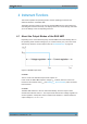
3.4.2 Means of Manual Interaction
To configure the R&S HMP manually, use the front panel controls, see Chapter 3.2,
"Instrument Tour", on page 21. The display shows the current settings, menus and dia-
logs, when you perform your settings.
This section briefly explains the controls and some additional features, e.g.:
●
The use of the arrow keys or alternatively the rotary knob to adjust settings.
●
The meaning of the color of the channel keys (Ch1, ...).
Understanding the display information
Brief overview of the displayed elements:
●
Home screen: Displays the channel parameters.
●
Menus: Lists functions leading to the setting dialogs.
●
Dialogs: Provide the settings of the specific functions.
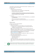
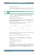
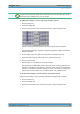
Illuminated keys
The illuminated front panel keys provide access to the instrument settings and to acti-
vate functions and operating modes. The channel keys illuminate in varying colors indi-
cating their current activities or states.
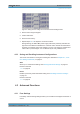
Figure 3-5: Example of the illuminated channel and output keys of the R&S
HMP4040
Meaning of the key colors:
●
White: the function or operating mode is activated.
●
Green (channel key): the channel is in constant voltage mode (CV).
●
Red (channel key): the channel is in constant current mode (CC), i.e. the current
limit is active.
●
Blue (channel key): the channel is in setting mode, i.e. a function is activated.
●
Flashing (channel key): if the Output key and the Voltage key are active, and you
change a setting of a channel, the color changes depending on the operating
mode:
– Blue / Green flashing: CV = constant voltage.
– Blue / Red flashing: CC = constant current.
●
Off: the channel, function, or operating mode are not active.
Instrument Control