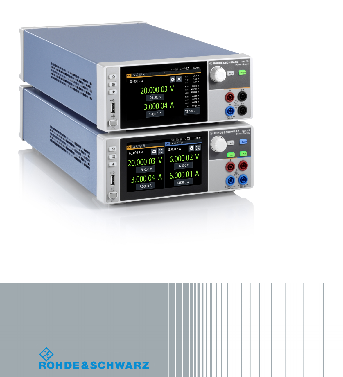
R&S®NGL200 Power Supply User Manual (;ÜåT2) Version 02.
This manual describes the following R&S®NGL200 models and options: ● R&S®NGL201 1 Channel PSU 60W (3638.3376.02) ● R&S®NGL202 2 Channel PSU 120W (3638.3376.03) ● R&S®NGL-K102 Option Wireless LAN (3652.6362.02) ● R&S®NGL-K103 Option Digital I/O (3652.6385.02) ● R&S®NGL-B105 Option GPIB Interface (3652.6356.02) The contents of this manual correspond to firmware version 1.00 or higher. The software contained in this product uses several valuable open source software packages.
Safety Instructions Instrucciones de seguridad Sicherheitshinweise Consignes de sécurité Risk of injury and instrument damage The instrument must be used in an appropriate manner to prevent electric shock, fire, personal injury or instrument damage. ● Do not open the instrument casing. ● Read and observe the "Basic Safety Instructions" delivered as printed brochure with the instrument. ● Read and observe the safety instructions in the following sections.
Gefahr von Verletzungen und Schäden am Gerät Betreiben Sie das Gerät immer ordnungsgemäß, um elektrischen Schlag, Brand, Verletzungen von Personen oder Geräteschäden zu verhindern. ● Öffnen Sie das Gerätegehäuse nicht. ● Lesen und beachten Sie die "Grundlegenden Sicherheitshinweise", die als gedruckte Broschüre dem Gerät beiliegen. ● Lesen und beachten Sie die Sicherheitshinweise in den folgenden Abschnitten; möglicherweise enthält das Datenblatt weitere Hinweise zu speziellen Betriebsbedingungen.
Customer Support Technical support – where and when you need it For quick, expert help with any Rohde & Schwarz equipment, contact one of our Customer Support Centers. A team of highly qualified engineers provides telephone support and will work with you to find a solution to your query on any aspect of the operation, programming or applications of Rohde & Schwarz equipment.
R&S®NGL200 Contents Contents 1 Preface.................................................................................................... 7 1.1 Documentation Overview............................................................................................. 7 1.1.1 Manuals and Instrument Help......................................................................................... 7 1.1.2 Data Sheet.....................................................................................................
R&S®NGL200 Contents 4.3 Trying Out the Instrument.......................................................................................... 24 4.3.1 Setting the Output Voltage and Current........................................................................ 24 4.3.2 Activating the Channels Output.....................................................................................24 4.4 Maintenance.....................................................................................................
R&S®NGL200 Contents 6.3.3 Over Power Protection (OPP)....................................................................................... 47 6.3.4 Safety Limits..................................................................................................................48 6.4 Advanced Features..................................................................................................... 49 6.4.1 Arbitrary..................................................................................
R&S®NGL200 Contents 7.5.2 Voltage Setting.............................................................................................................. 87 7.5.3 Current Setting.............................................................................................................. 91 7.5.4 Resistance Setting........................................................................................................ 95 7.5.5 Combined Setting of Voltage and Current Setting............................
R&S®NGL200 Preface Documentation Overview 1 Preface 1.1 Documentation Overview This section provides an overview of the R&S NGL200 user documentation. 1.1.1 Manuals and Instrument Help You find the manuals on the product page at: www.rohde-schwarz.com/product/ngl200 Getting started manual Introduces the R&S NGL200 and describes how to set up the product. A printed English version is included in the delivery. User manual Contains the description of all instrument modes and functions.
R&S®NGL200 Preface Conventions Used in the Documentation 1.1.3 Release Notes and Open Source Acknowledgment The release notes list new features, improvements and known issues of the current firmware version, and describe the firmware installation. The open source acknowledgment document provides verbatim license texts of the used open source software. See www.rohde-schwarz.com/firmware/ngl200. The open source acknowledgment document can also be read directly on the instrument. 1.
R&S®NGL200 Preface Conventions Used in the Documentation 1.2.3 Notes on Screenshots When describing the functions of the product, we use sample screenshots. These screenshots are meant to illustrate as many as possible of the provided functions and possible interdependencies between parameters. The shown values may not represent realistic usage scenarios. The screenshots usually show a fully equipped product, that is: with all options installed.
R&S®NGL200 Welcome to R&S NGL200 2 Welcome to R&S NGL200 The one or two-channel power supply series are based on a classical transformer concept with linear regulators. This concept allows the instrument to achieve highest accuracy and lowest residual ripple. The R&S NGL200 power supply series feature galvanically isolated, floating overload and short-circuit proof outputs. The outputs can be connected in parallel and serial to get higher voltages, thus making high currents available.
R&S®NGL200 Important Notes Ambient Conditions 3 Important Notes 3.1 Symbols Caution, general danger zone Ground PE terminal ON (supply voltage) OFF (supply voltage) Ground terminal 3.2 Ambient Conditions The allowed operating temperature ranges from +5 °C to +40 °C (pollution category 2). The maximum relative humidity (without condensation) is at 80 %. During storage and transport, the temperature must be between -40 °C and +70 °C.
R&S®NGL200 Important Notes Mains Voltage ~72 °C, a channel-specific overheat protection intervenes. Affected outputs will automatically be switched off. Air circulation Do not obstruct the ventilation holes! 3.3 Measurement Categories This instrument is designed for supplying power on circuits that are only indirectly connected to the low voltage mains or not connected at all.
R&S®NGL200 Important Notes Limits circuiting the fuse holder is prohibited. Resulting damages are not covered by the warranty. Safe operation If the instrument is to remain unattended for a longer time period, it must be switched off at the mains switch for safety reasons. 3.5 Limits The R&S NGL200 is equipped with a protective overload feature. The protective overload feature prevents damage to the instrument and is intended to protect against a possible electrical shock.
R&S®NGL200 Getting Started Putting into Operation 4 Getting Started 4.1 Putting into Operation This chapter describes the steps to set up the R&S NGL200 for the first time. Risk of injury and instrument damage The instrument must be used in an appropriate manner to prevent electric shock, fire, personal injury, or damage. ● Do not open the instrument casing ● Read and observe the "Basic Safety Instructions" delivered as a printed brochure with the instrument.
R&S®NGL200 Getting Started Putting into Operation EMI impact on measurement results Electromagnetic interference (EMI) may affect the measurement results. To suppress the generated EMI: ● Use suitable shielded cables of high quality, for example, LAN cables ● Note the EMC classification in the data sheet ● ● ● ● Safety......................................................................................................................15 Intended Operation..............................................
R&S®NGL200 Getting Started Putting into Operation – After an extended period of storage under unfavorable conditions (e.g. outdoors or in damp rooms) – After rough handling during transport (e.g. packaging that does not meet the minimum requirements by post office, railway or forwarding agency) Exceeding the low voltage protection Use insulated wires and not bare wires for the terminal connection.
R&S®NGL200 Getting Started Putting into Operation To disconnect from the mains, unplug the IEC socket on the back panel. See Table 4-1 for the general data on the instrument specification. For more information, see the instrument datasheet (PN: 5216.1057.12). Table 4-1: General data on instrument specification General data Mains nominal voltage AC 100 / 115 / 230 V (±10 %) 50 Hz to 60 Hz Maximum input power 400 W Mains fuses IEC 60127-2 / 5 T4.
R&S®NGL200 Getting Started Putting into Operation Risk of damage during transportation and shipment Insufficient protection against mechanical and electrostatic effects during transportation and shipment can damage the instrument. ● Always ensure that sufficient mechanical and electrostatic protection are provided ● When shipping an instrument, the original packaging should be used.
R&S®NGL200 Getting Started Instrument Tour Positioning of instrument The instrument must be positioned in a manner that allows the user to disconnect the unit from the mains at any time and without restrictions. 4.1.4.2 Rack Mounting The instrument can be installed in a 19 " rack-mount using a rack adapter kit. Ambient temperature Place the R&S NGL200 in an area where the ambient temperature is within +5 °C to +40 °C.
R&S®NGL200 Getting Started Instrument Tour Figure 4-2: Front panel of R&S NGL200 1 2 3 4 5 6 7 = = = = = = = Display with touch screen Menu control keys Navigation keys Output and channels keys Output terminals (one channel with sense NGL201, two channels NGL202) USB connector Power key Display (1) The display is a color LCD screen. Depending on the instrument model, up to two channels are shown on the display.
R&S®NGL200 Getting Started Instrument Tour Each channel is capable to source 0 V to 6 V with a current of 6 A or 6 V to 20 V with a current of 3 A. In sink mode, each channel can consume 0 A to 3 A at an input voltage of 0 V to 20 V. Output terminals (5) Both instrument models are equipped with 4 terminals. The R&S NGL201 provides both the output plus the sense connectors at the front panel while the R&S NGL202 provides only output terminals for both channels.
R&S®NGL200 Getting Started Instrument Tour AC inlet with fuse holder and voltage selector (8) Main supply cord Do not use detachable mains supply cord with inadequate rating. For safety reasons, the instrument can only be operated with authorized safety sockets. The power cable must be plugged in before signal circuits can be connected. Never use the product if the power cable is damaged. See Chapter 4.2.2, "Switching On the Instrument", on page 23 for more information.
R&S®NGL200 Getting Started Instrument Tour Digital I/O connector (15) The Digital I/O connector is a terminal block for external input or output. The Digital Trigger I/O option (NGL-K103) must be installed for this function to be available in the instrument. 4.2.2 Switching On the Instrument Before switching on the instrument, check if the value on the voltage selector corresponds to the mains voltage (100 V, 115 V or 230 V). Switch it on, if necessary.
R&S®NGL200 Getting Started Trying Out the Instrument 2. Disconnect the AC power cable from the AC power supply. 4.3 Trying Out the Instrument This chapter describes some basic functions that you can perform with the R&S NGL200. Source and sink current The R&S NGL200 series are 2 quadrant power supplies which may both source and sink current. This function needs no separate configuration or mode switching.
R&S®NGL200 Getting Started Maintenance CR mode CR mode is a special case of sink mode in which the instrument behaves like a constant resistor. Only in this mode, the respective channel keys and display font color in the home window turns cyan. In "normal" sink mode, the colors are the same as in source mode: green if the current flowing into the R&S NGL200 is below the set current and red if the current is limited to the set value.
R&S®NGL200 Operating Basics Display Overview 5 Operating Basics 5.1 Display Overview The following displays the home window of R&S NGL200. It shows the output voltage and current level, status bar information and control settings of the instrument.
R&S®NGL200 Operating Basics Display Overview Device status bar Function Description GPIB/IEEE488 interface If GPIB/IEEE488 interface is installed, the icon is highlighted in white. SCPI command If active, the icon is highlighted in white. If an error is in the remote command, the icon is highlighted in red. See Chapter 7, "Remote Control Commands", on page 79. USB host interface If USB stick is present, the icon is highlighted in white.
R&S®NGL200 Operating Basics Display Overview Function Description "Over Voltage Protection" (OVP), If enabled, the icon is highlighted in white. If triggered, the icon blinks. See Chapter 6.3.2, "Over Voltage Protection (OVP)", on page 46. "Over Power Protection" (OPP), If enabled, the icon is highlighted in white. If triggered, the icon blinks. See Chapter 6.3.3, "Over Power Protection (OPP)", on page 47. "Arbitary Editor" mode, If enabled, the icon is highlighted in white.
R&S®NGL200 Operating Basics Display Overview 1 2 3 4 5 6 7 8 = = = = = = = = Display output power in Watt Display constant resistance in Ohms Settings button which opens instrument main menu window Expand/Collapse channel button which toggles between home window and channel overview window Output voltage displays in Volt. The display resolution for voltage is five digits after the decimal point Set voltage level.
R&S®NGL200 Operating Basics Using the Touchscreen Color Operating mode Description CC mode Active outputs are operated in a constant current mode CR mode Active outputs are operated in a constant resistance mode. This condition occurs if the set voltage is below the voltage applied externally at the output connectors (sink mode) and constant resistor is switched on in channel menu. 5.2 Using the Touchscreen The R&S NGL200 provides a touch-sensitive screen which can be disabled (seeChapter 6.
R&S®NGL200 Operating Basics Using the Touchscreen Figure 5-3: Navigation on home window>main menu window>channel menu window 5.2.2.2 Voltage and Current Buttons You can directly change the voltage and current level in the respective channel display area. 1. Select the voltage or current field in the channel display area. The R&S NGL200 displays the on-screen keypad to enter value. 2. Set the required value. See Chapter 5.2.3, "Input Data", on page 32.
R&S®NGL200 Operating Basics Using the Touchscreen Figure 5-4: Set voltage and current in home window 5.2.2.3 Expand/Collapse Button You can expand the selected channel window by using the expand/collapse button. The expand/collapse channel icon changed when toggled. 1. Select the expand/collapse button. The R&S NGL200 expands the selected channel window. 2. Select the expand/collapse button to revert to the home window.
R&S®NGL200 Operating Basics Front Panel Keys 3. Confirm value with the unit key. Alternatively, select the "tick" key to confirm your value. Figure 5-6: Enter numerical value and unit For alphanumeric input, the on-screen keypad works the same way. 1. Select the arrow key to switch between capital letters and small letters. The arrow key toggles between displaying in green and gray. 2. Select "&123" or "ABC" key to switch between alphabet and numeric input data. Figure 5-7: Alphanumeric input data 5.
R&S®NGL200 Operating Basics Front Panel Keys 5.3.1 Menu Controls The menu controls keys provide navigation on the available menus in the instrument. 5.3.1.1 Home Button Navigate to the instrument home window. See Figure 5-1. 5.3.1.2 Settings Button Navigate to the main menu window which consists of the "Device" menu and up to two channels ("Channel 1", "Channel 2") menu.
R&S®NGL200 Operating Basics Front Panel Keys Menus Description "Arb Editor" Programs the waveform of voltage and current settings for the channel output. "Logging" Data logging on the instrument timestamp, voltage and current. "Trigger" Activates the trigger source for SCPI command (*TRG). "User Button" Configures the shortkey key action (screenshot, trigger, toggle logging, reset statistics, toggle touch). "File Manager" File transfer function between instrument internal memory and USB stick.
R&S®NGL200 Operating Basics Front Panel Keys 5.3.1.3 Menus Description "Over Protection Protection (OPP)" Configures OPP protection settings (OPP power) for the instrument. "Arbitrary" Selects the file used in the arbitrary function. "Ramp" Configures ramping time apply on the channel output. "Output" Configures the output impednace, output delay time before voltage is output on the channel and the trigger action on output when activated.
R&S®NGL200 Operating Basics Output Modes 5.3.3 Output and Channel Controls Only applicable for R&S NGL202, these keys control the channel output settings of the instrument. Function keys Description [Ch1], [Ch2] Selects the respective channel for output. [Output] Toggles the selected channel output on or off. 5.4 Power Derating The NGL202 includes two identical channels with a continuous voltage range of 0 V to 20 V.
R&S®NGL200 Operating Basics Output Modes See Figure 5-2. Figure 5-10: Current limit CC mode The current Imax corresponds to the current setting adjustable in the instrument. If Iout reaches Imax, the instrument switches to CC mode, i.e. the output current remains constant and limited to Imax even if the load increases. Instead, the output voltage Vout decreases to almost zero with a short circuit. In CC mode, the font text in the channel display area changes to red. See Figure 5-2.
R&S®NGL200 Instrument Functions Setting the Channels Voltage and Current 6 Instrument Functions 6.1 Setting the Channels Voltage and Current NGL202 comes with two channels and NGL201 comes with single channel. Toggle the respective channel key ([Ch1],[Ch2] ) on the front panel to select these channels. When a channel is selected, the respective channel key illuminates.
R&S®NGL200 Instrument Functions Activating the Channels Output Figure 6-2: Voltage and current settings in the instrument 6.2 Activating the Channels Output The outputs of all the channels (Ch1, Ch2) can be switched on or off by toggling the [Output] key on the front panel. By default, the output is turned off when the instrument is switched on. The output is also automatically turned off when no channel is selected. This design prevents a connected load from being damaged unintentionally. 1.
R&S®NGL200 Instrument Functions Activating the Channels Output Figure 6-3: Output of Ch2 in CV mode Multiple outputs can be turned on or off at the same time. See also Chapter 5.4, "Power Derating", on page 37. 6.2.1 Set Constant Resitance By enabling the constant resistance (CR) mode, you can operate the R&S NGL200 as an electronic load in sink mode. This allows you to perform testing that requires a constant load resistor in your application. 1. Press [Settings] key.
R&S®NGL200 Instrument Functions Activating the Channels Output Figure 6-4: Constant resistance dialog 6.2.2 Fast Transient Response With fast transient response, the R&S NGL200 is able to quickly stabilize the output voltage upon a step change in the load current.
R&S®NGL200 Instrument Functions Activating the Channels Output The R&S NGL200 applies the fast transient response on the operating condition and displays the "Fast Transient Response" icon on the selected channel status bar information. 6.2.3 Output The "Output" dialog provides the settings for output impedance, output delay and trigger action on the output mode.
R&S®NGL200 Instrument Functions Activating the Channels Output Figure 6-7: Output delay dialog 4. Select the "Impedance", "Delay" and "Trigger" menu items to configure the required values. The R&S NGL200 displays an on-screen keypad to set the value for output impedance and output delay. For setting trigger mode, the R&S NGL200 displays a "Select Trigger" dialog to set the trigger mode. ● ● ● ● Disabled: If triggered, the selected output channel is disabled.
R&S®NGL200 Instrument Functions Protection Figure 6-8: Delay text at channel display area 6.3 Protection There are various ways in which the R&S NGL200 protects itself and the connected load from damage due to overvoltage, overcurrent and overpower drawn by the load during testing. 6.3.
R&S®NGL200 Instrument Functions Protection Figure 6-9: Over current protection dialog 4. Activate the "Enabled" menu item. The R&S NGL200 enables the OCP and displays the "Over Current Protection (OCP)" icon on the selected channel status bar information. 5. Set the required "Blowing Delay" and "Initial Delay". The R&S NGL200 displays an on-screen keypad to set the value. a) "Blowing Delay": The time taken to turn off the affected channel after OCP is triggered.
R&S®NGL200 Instrument Functions Protection Figure 6-10: Over voltage protection dialog 4. Activate the "Enabled" menu item. The R&S NGL200 enables the OVP and displays the "Over Voltage Protection (OVP)" icon on the selected channel status bar information. 5. Set the required level for OVP. The R&S NGL200 displays an on-screen keypad to set the value. 6. Confirm value with the unit key (mV or V). 6.3.
R&S®NGL200 Instrument Functions Protection Figure 6-11: Over power protection dialog 4. Activate the "Enabled" menu item. The R&S NGL200 enables the OPP and displays the "Over Protection Protection (OPP)" icon on the selected channel status bar information. 5. Set the required level for OPP. The R&S NGL200 displays an on-screen keypad to set the value. 6. Confirm value with the unit key (mW or W). 6.3.
R&S®NGL200 Instrument Functions Advanced Features Figure 6-12: Safety limits dialog 4. Activate the "Enabled" menu item. The R&S NGL200 limits the set voltage and current level and displays the "Safety Limits" icon on the selected channel status bar information. 5. Set the required minimum and maximum voltage and current level. The R&S NGL200 displays an on-screen keypad to set the value. 6. Confirm value with the unit key. 6.
R&S®NGL200 Instrument Functions Advanced Features Figure 6-13: Select source and file location 4. Activates the "Enabled" menu item. The R&S NGL200 enables the arbitrary function and displays the "Arbitrary" icon on the selected channel status bar information. 5. Selects "Load from file.." to load the arbitrary file. The R&S NGL200 opens a dialog to select the source and file location. 6. Selects the required source and file location. Alternatively, select "New file" to edit a new arbitrary file.
R&S®NGL200 Instrument Functions Advanced Features ● 6.4.1.1 "Step triggered": If triggered, every arbitrary step needs a trigger signal to execute (note: step time from "Arb Editor" is ignored). Arbitrary Editor To edit the arbitrary file: 1. Press [Settings] key. The R&S NGL200 displays the main menu window. 2. Select "Device" tab to edit the arbitrary file. The R&S NGL200 displays the "Device" menu. 3. Select "Arb Editor" from the menu The R&S NGL200 displays the "Arb Editor" dialog. 4.
R&S®NGL200 Instrument Functions Advanced Features The R&S NGL200 opens the arbitrary editor dialog to edit the arbitrary file. Figure 6-14: Arbitrary editor dialog 7. Configure the "Arb Editor" with the required voltage, current and duration. The R&S NGL200 displays the on-screen keypad for data entry. 8. Confirm values with the unit keys. 9. Select the interpolation checklist to toggle on/off the interpolation function on the arbitrary data. 10.
R&S®NGL200 Instrument Functions Advanced Features 6.4.2 Ramp The Ramp function provides you the operating condition to output a constant rise of the supply voltage within a set timeframe. The output voltage can be increased continuously within a 10 ms to 10 s timeframes. See Figure 6-15 Figure 6-15: Ramping voltage output 1. Press [Settings] key. The R&S NGL200 displays the main menu window. 2. Select the required channel tab to configure ramp function. The R&S NGL200 displays the selected channel menu.
R&S®NGL200 Instrument Functions Advanced Features Figure 6-16: Ramp dialog 4. Activate the "Enabled" menu item. The R&S NGL200 enables the ramping function and displays the "Ramp" icon on the selected channel status bar information. 5. Enter the required ramping time. The R&S NGL200 displays an on-screen keypad to set the value. 6. Confirm value with the unit key. 6.4.3 Digital I/O Digital I/O Pins Voltage Rating Do not exceed the maximum voltage rating of the Digital I/O pins (5.
R&S®NGL200 Instrument Functions Advanced Features Figure 6-17: Overview of trigger IO system Red lines = Hardware function Black line = Software function Blue = Option is not required for these trigger-in signals Table 6-1: Trigger-in signals Trigger-in parameters Source Descriptions Inhibit Ch1 Pin 1 of DIO connector Inhibit Ch2 Pin 2 of DIO connector If detected, respective channel output is turned off if the inhibit goes active.
R&S®NGL200 Instrument Functions Advanced Features Table 6-2: Trigger-out signals Trigger-out parameters Trigger conditions Descriptions Output channel Output On If a trigger is detected, respective channel output of the instrument turns on or off. Output Off Gated Digital Output Fault CC, CV, CR, Protection and Sink If respective channel output modes, protection event or sink mode is detected, a trigger signal is sent out at pin 11 of the DIO connector.
R&S®NGL200 Instrument Functions Advanced Features Table 6-3: DIO pin layout Pin Signal Direction Pin Signal Direction 1 Inhibit Ch1 Trigger in signal 9 Inhibit Ch2 Trigger in signal 2 Trigger Ch1 Trigger in signal 10 Trigger Ch2 Trigger in signal 3 In Trigger in signal 11 Output Fault Trigger out signal 4 Out1 Trigger out signal 12 Out2 Trigger out signal 5 Gnd - 13 Gnd - 6 Gnd - 14 Gnd - 7 Gnd - 15 Gnd - 8 Gnd - 1. Press [Settings] key.
R&S®NGL200 Instrument Functions Advanced Features Figure 6-20: Digital Out dialog 7. Depending on your requirement, select the digital output accordingly. See Table 6-2 for details of the trigger-out parameters. 8. Select the respective "Digital Output" menu items and set "On" to enable the trigger-out parameters. 9. Select "Back" to go back to "Device" menu. 10. If "User Button" is set as a trigger-in signal, select "User Button" menu item. The R&S NGL200 displays the "User Button" dialog.
R&S®NGL200 Instrument Functions User Button Key 6.5 User Button Key The R&S NGL200 allows you to configure the user key action for one of the following functions: ● Screenshot image from instrument ● Instrument trigger function ● Toggle data logging function ● Reset sample count (see index 4 of Figure 5-5) ● Toggle touchscreen function 1. Press [Settings] key. The R&S NGL200 displays the main menu window. 2. Select the "Device" menu tab to configure user key.
R&S®NGL200 Instrument Functions Screenshot 6.6 Screenshot With screenshot, you can capture image easily from the instrument. The images can be stored in the USB stick or internal memory of the instrument. By default, the screen images are stored in the USB device under the target folder: /USB1A/NGL202/ screenshot. 1. Press [Settings] key. The R&S NGL200 displays the main menu window. 2. Select the "Device" tab to configure screenshot file location. The R&S NGL200 displays the device menu. 3.
R&S®NGL200 Instrument Functions Data Logger 6.7 Data Logger When data logging is activated, the R&S NGL200 records the voltage and current data and stores it in the predefined target folder. The data can be stored in the USB stick or in the internal memory. By default, data is stored in the USB device under the target folder: /USB1A/NGL202/logging. The Logging dialog 1. Press [Settings] key. The R&S NGL200 displays the main menu window. 2. Select the "Device" tab to configure data logger.
R&S®NGL200 Instrument Functions Data Logger Figure 6-23: Target folder dialog ● ● "USB1A": Target folder is set to /USB1/NGM202/logging. "int": Target folder is set to /int/logging. 7. Set the required target folder. 8. Select "Set" to confirm the selection. 9. Select "Mode" to set logging duration. ● ● ● ● "Duration": Time taken for data logging with duration and time interval setting.
R&S®NGL200 Instrument Functions Data Logger A CSV file stores tabular data (numbers and text) in plain text. Each line of the file is a data record and each record consists of one or more fields, separated by a file delimiter. The "CSV Settings" provides you ways to format the fields that are stored in the data logging. See Figure 6-24 Figure 6-24: Sample of data logging 1. Select "CSV Settings" from "Device" menu or "Logging" menu in respective channel menu...
R&S®NGL200 Instrument Functions File Manager 3. Set the required value. 4. Select "Set" to confirm the value. Table 6-4: CSV settings CSV Settings Selective fields in the dialog Field Delimiter "Comma", "Semicolon" Decimal Separator "Dot", "Comma" Error Designator "IEE Float (NaN)", "Empty" Line End Marker "CR/LF", "LF" 6.8 File Manager The "File Manager" provides the files transfer function between USB stick and the internal memory of the instrument.
R&S®NGL200 Instrument Functions Store and Recall Table 6-5: File manager action Action Description Copy from internal memory to USB. Copy from USB to internal memory. Delete the selected file. 6.9 Store and Recall Upon power-up, the instrument loads the last stored settings from internal memory location. Auto saved parameters are also applied during startup. The R&S NGL200 output states of all channels (Ch1, Ch2) are disabled when the recall function is activated.
R&S®NGL200 Instrument Functions Store and Recall Figure 6-27: Save/Recall device settings dialog 4. Select "Save Settings to file" to save current instrument settings. The R&S NGL200 opens a dialog to select source and file location. You can save to existing file or create a file for saving. 5. Set the source and file location. The R&S NGL200 save the current instrument settings. 6. Similar, you can select "Recall Settings from file." to load instrument settings.
R&S®NGL200 Instrument Functions Interfaces 6.10 Interfaces There are various of ways how the R&S NGL200 can be remotely access and controlled. 1. Press [Settings] key. The R&S NGL200 displays the main menu window. 2. Select the "Device" tab to configure network connection. The R&S NGL200 displays the device menu. 3. Select "Interfaces". The R&S NGL200 displays the "Interfaces" dialog. Figure 6-28: Interfaces dialog 4.
R&S®NGL200 Instrument Functions Interfaces 6.10.1 Network Connection There are two methods to establish a local area network (LAN) connection with the R&S NGL200 for remote control operation. ● LAN ● Wireless LAN 1. Select "Network" from the Figure 6-28. The R&S NGL200 displays the "Network" dialog. Figure 6-29: Network dialog 2. Set the required "SCPI Raw Port" and "Hostname". The R&S NGL200 displays the on-screen keypad to enter the port number and hostname.
R&S®NGL200 Instrument Functions Interfaces To establish a network connection, connect a commercial RJ-45 cable to the LAN port of the instrument and to a PC. Depending on the network capacities, the TCP/IP address information for the instrument can be obtained in different ways. ● If the network supports dynamic TCP/IP configuration using the Dynamic Host Configuration Protocol (DHCP), and a DHCP server is available, all address information can be assigned automatically.
R&S®NGL200 Instrument Functions Interfaces ● ● "ON": Enables DHCP for automatic network parameter distribution and shows the values of the IP Address. By default, the instrument is configured to use dynamic configuration and obtain all address information automatically. "OFF": To be used if the network does not support dynamic host configuration protocol (DHCP). The addresses must be set manually. 4. Set the required DHCP mode.
R&S®NGL200 Instrument Functions Interfaces Figure 6-32: WLAN settings dialog 2. Select "Enable" menu item to set "On" to enable wireless LAN. The R&S NGL200 began searching available WiFi network and the "Status" shows "Searching". 3. Select the "Select Network" to connect the required WiFi network. If connection is successful, the "Status" shows "Connected". See Figure 6-33. When the connection is alive, the WLAN icon turns white on the device status bar. See device status bar.
R&S®NGL200 Instrument Functions Interfaces Figure 6-34: USB dialog 2. Set the USB class. 3. Select "Set" to confirm the selection. 6.10.3 GPIB Address R&S NGL-B105 (3652.6356.02) option is required to install for the remote command of R&S NGL200 via GPIB interface. The GPIB interface, sometimes called the General Purpose Interface Bus (GPIB), is a general purpose digital interface system that can be used to transfer data between two or more devices.
R&S®NGL200 Instrument Functions General Instrument Settings 2. Enter the required value. 3. Confirm value with the enter key 6.11 General Instrument Settings The following chapters provide the general instrument information and utilities services in "Device" menu. 1. Press [Settings] key. The R&S NGL200 displays the main menu window. 2. Select the "Device" tab. The R&S NGL200 displays the device menu. 6.11.1 Licenses Options are enabled by entering a registered license key code.
R&S®NGL200 Instrument Functions General Instrument Settings Figure 6-35: License dialog To install an xml file, proceed as follows: 1. Copy the xml file containing the registered key code into the USB flash drive. 2. Connect the USB flash drive to the USB port of the instrument. 3. Select "Load File" to load the license file from the USB stick. 4. Select the license file to install in the instrument. The R&S NGL200 install the license option accordingly.
R&S®NGL200 Instrument Functions General Instrument Settings 3. Confirm entry with the enter key . If the correct key code is entered, the R&S NGL200 popup a message "Devicekey is installed" and the option is displayed in the "Active" window. 4. To remove the option, select "Remove" from the license dialog. The R&S NGL200 displays the license key on-screen keyboard. See Figure 6-36. 5. Enter the key code (30-digit number) of the option in the entry box. 6. Confirm entry with the enter key .
R&S®NGL200 Instrument Functions General Instrument Settings Figure 6-38: Sound settings dialog 2. Select the required fields to set alert. ● ● ● "Error Beep": A single beep alert when error occurs. "Fuse Tripped Beep": A single beep alert when a fuse tripped occurs. See Chapter 6.3, "Protection", on page 45. "CC-Mode Continuous Beep": A continue beep sound alert when the selected output channel go into CC mode. See CC mode. 6.11.4 Date and Time 1. Select the "Date & Time" to set date and time format.
R&S®NGL200 Instrument Functions General Instrument Settings The R&S NGL200 reset the instrument date and time accordingly. 6.11.5 Device Information General instrument information of R&S NGL200. ► Select the "Instrument Information" to display the device information. The R&S NGL200 displays the device information dialog. Figure 6-40: Device information dialog Device information Description Model Model of the instrument, i.e NGL201 or NGL202 ID Instrument orderable part number. Serial No.
R&S®NGL200 Instrument Functions General Instrument Settings 1. Select the "Update Device" to update instrument firmware. The R&S NGL200 displays the update device dialog. Figure 6-41: Update device dialog 2. Select the source and file location to update instrument firmware. 3. Select "UPDATE" to update the instrument firmware. The R&S NGL200 update the instrument firmware accordingly. User Manual 1178.8736.02 ─ 02.
R&S®NGL200 Remote Control Commands Common Setting Commands 7 Remote Control Commands This chapter provides the description of all remote commands available for the R&S NGL200 series. The commands are sorted according to the menu structure of the instrument. A list of commands in alphabetical order is given in the "List of Commands" at the end of this documentation. 7.1 Common Setting Commands Common commands are described in the IEEE 488.2 (IEC 625-2) standard.
R&S®NGL200 Remote Control Commands Common Setting Commands *ESR? Event status read Returns the contents of the event status register in decimal form and then sets the register to zero. Return values: Range: Usage: Query only 0 to 255 *IDN? Identification Returns the instrument identification.
R&S®NGL200 Remote Control Commands Common Setting Commands *STB? Status byte query Reads the contents of the status byte in decimal form. Usage: Query only *TRG Recall Triggers all actions waiting for a trigger event. In particular, *TRG generates a manual trigger signal. This common command complements the commands of the TRIGger subsystem. Usage: Event *TST? Self-test query Initiates self-tests of the instrument and returns an error code.
R&S®NGL200 Remote Control Commands System Settings Commands *RCL Recall Loads the instrument settings from an internal memory identified by the specified number. The instrument settings can be stored to this memory using the command *SAV with the associated number. 7.2 System Settings Commands The SYSTem subsystem contains the commands for general functions, which do not affect signal generation directly. SYSTem:BEEPer:STATe........................................................................
R&S®NGL200 Remote Control Commands System Settings Commands SYSTem:REMote Sets the system to remote state. The front panel control is locked. By pushing the softkey button UNLOCK KEYS the front panel control will be activated. Usage: Setting only SYSTem:RWLock Sets the system to remote state. The front panel control is locked and a message box is shown on the NGL display. You are only able to unlock the front panel control via SCPI command SYSTem:LOCal.
R&S®NGL200 Remote Control Commands Display Commands Parameters: Sets the hours of the system time. Sets the minutes of the system time. Sets the seconds of the system time. Example: SYSTem:TIME 12, 30, 59 SYSTem:TIME? -> 12, 30, 59 Returns system time. 7.3 Display Commands The DISPlay subsystem contains the commands for display functions, which do not affect signal generation directly. DISPlay:BRIGhtness................................................................................
R&S®NGL200 Remote Control Commands Configuration Commands 7.4 Trigger Commands The TRIGger subsystem contains the commands for signal triggering. TRIGger:SLOPe.............................................................................................................. 85 TRIGger:SLOPe Sets/Queries the type of external trigger input. Parameters: POSitive | NEGative POSitive Rising edge of the external trigger input. NEGative Falling edge of the external trigger input.
R&S®NGL200 Remote Control Commands Configuration Commands Example: Selecting a channel You can select a channel either with an OUTput parameter, or just by the channel number. This example lists all ways how you can select and query a selected channel.
R&S®NGL200 Remote Control Commands Configuration Commands 7.5.2 Voltage Setting The SOURce:VOLTage subsystem contains the commands for setting the voltage of the output channels. The default unit is V. User Manual 1178.8736.02 ─ 02.
R&S®NGL200 Remote Control Commands Configuration Commands Example: Configuring the output voltage This example contains all commands to configure and query the output voltage.
R&S®NGL200 Remote Control Commands Configuration Commands // selects the output channel, sets the step width // and increases the voltage in the selected channel // by the set 4 Volts VOLT DOWN // decreases the voltage in the selected channel // by the set 4 Volts VOLT:STEP? // queries the voltage step size // repsonse: "4.000" [SOURce:]ALIMit[:STATe]..................................................................................................89 [SOURce:]VOLTage[:LEVel][:IMMediate]:ALIMit:LOWer......
R&S®NGL200 Remote Control Commands Configuration Commands [SOURce:]VOLTage[:LEVel][:IMMediate]:ALIMit[:UPPer] [SOURce:]VOLTage[:LEVel][:IMMediate]:ALIMit[:UPPer]? Sets/Queries the upper safety limit for voltage. Setting parameters: numeric | MIN | MAX numeric Numeric value for upper safety limit. MIN Min value for upper safety limit. MAX Max value for upper safety limit. Range: 0.000E+00 to 2.000E+01 Increment: 0.001 *RST: 2.
R&S®NGL200 Remote Control Commands Configuration Commands [SOURce:]VOLTage[:LEVel][:IMMediate]:STEP[:INCRement] [SOURce:]VOLTage[:LEVel][:IMMediate]:STEP[:INCRement]? [] Sets/Queries the incremental step size for the VOLT UP | VOLT DOWN command. Setting parameters: numeric | DEFault numeric Step value in V. DEFault Default value of stepsize. Range: Increment: *RST: Default unit: Query parameters: 0.001 to 5.000 0.001 0.
R&S®NGL200 Remote Control Commands Configuration Commands Example: Configuring the current limit // ************************************************ // Select the channel // ************************************************ INST OUT1 // ************************************************ // Set upper or lower current safety limit // ************************************************ ALIM 1 //sets the safety limits to enable ALIM? //queries the safety limits state //response: "1" VOLT:ALIM 6 //sets the safety li
R&S®NGL200 Remote Control Commands Configuration Commands // by the set 1 Ampere CURR:STEP? // queries the current step size // repsonse: 1.000 [SOURce:]CURRent[:LEVel][:IMMediate]:ALIMit:LOWer.......................................................93 [SOURce:]CURRent[:LEVel][:IMMediate]:ALIMit[:UPPer]......................................................93 [SOURce:]CURRent[:LEVel][:IMMediate]:STEP[:INCRement]...............................................
R&S®NGL200 Remote Control Commands Configuration Commands [SOURce:]CURRent[:LEVel][:IMMediate]:STEP[:INCRement] [SOURce:]CURRent[:LEVel][:IMMediate]:STEP[:INCRement]? [] Sets/Queries the incremental step size for the CURR UP | CURR DOWN command. Setting parameters: numeric | DEFault numeric Step value in A. DEFault Default value of stepsize. Range: Increment: *RST: Default unit: Query parameters: 0.0001 to 2.000 0.0001 0.
R&S®NGL200 Remote Control Commands Configuration Commands DOWN Decrease current by a defined step size. See [SOURce: ]CURRent[:LEVel][:IMMediate]:STEP[:INCRement] on page 94. Query parameters: MIN | MAX MIN Return minimum current. MAX Return maximum current. See also Example "Configuring the current limit" on page 92. 7.5.4 Resistance Setting The SOURce:RESistance subsystem contains the commands for setting the resistance limit of the output channels. The default unit is ohms.
R&S®NGL200 Remote Control Commands Configuration Commands Example: Configuring the resistance limit // ************************************************ // Select the channel // ************************************************ INST OUT1 // ************************************************ // Set the resistance value // ************************************************ RES 10 // selects a channel and sets the resistance RES? // queries the current of the selected channel // response: 10.
R&S®NGL200 Remote Control Commands Configuration Commands DOWN Decrease resistance by a defined step size. Increment: 0.1 ohms Default unit: ohms Query parameters: MIN | MAX Return minimum or maximum resistance value. Example: See Example "Configuring the resistance limit" on page 96. [SOURce:]RESistance:STATe [SOURce:]RESistance:STATe? Activates/Deactivates or Queries the constant resistance mode. Parameters: OFF | ON | 0 | 1 OFF | 0 Deactivates constant resistance mode.
R&S®NGL200 Remote Control Commands Configuration Commands DEFault Default voltage. *RST: 1.000 Default unit: V numeric | MIN | MAX | DEFault numeric Numeric value for current in the range of 0.000 to 6.000. MIN Min current at 0.000 A. MAX Max value for current at 6.000 A. DEFault Numeric value for current. *RST: 1.
R&S®NGL200 Remote Control Commands Configuration Commands Example: Activating the channels You can activate a selected channel and turn on or off the outputs either individually or all outputs simultaneously. This example lists all ways how you can activate and query the outputs.
R&S®NGL200 Remote Control Commands Configuration Commands ON | 1 Switches on previous selected channels simultaneously. Example: See Example "Activating the channels" on page 99 OUTPut[:STATe] OUTPut[:STATe]? Switches ON/OFF or queries the output of the previous selected channels. Parameters: OFF | ON | 0 | 1 OFF | 0 Switches off previous selected channels. ON | 1 Switches on previous selected channels.
R&S®NGL200 Remote Control Commands Configuration Commands ON | 1 Activates output delay for the selected channel. Example: OUTPut:DELay 1 OUTPut:DELay? -> 1 Return output delay state as on. OUTPut:FTResponse OUTPut:FTResponse? Activates/Deactivates or queries the fast transient response. Parameters: OFF | ON | 0 | 1 OFF | 0 Deactivates fast transient response. ON | 1 Activates fast transient response.
R&S®NGL200 Remote Control Commands Configuration Commands OUTPut:IMPedance:STATe OUTPut:IMPedance:STATe? Activates/Deactivates or Queries the impedance target for the selected channel. Parameters: OFF | ON | 0 | 1 OFF | 0 Deactivates output impedance for the selected channel. ON | 1 Activates output impedance for the selected channel. Example: OUTPut:IMPedance 1 OUTPut:IMPedance:STAT? -> 1 Return output impedance state as on.
R&S®NGL200 Remote Control Commands Configuration Commands // selects a channel and activates the fuse FUSE? // queries the state of the fuse in the selected channel // response: 1 // ************************************************ // Set a delay time for the fuse. The delay time // takes effect when the channel output is turned on.
R&S®NGL200 Remote Control Commands Configuration Commands // response: 60000 // ************************************************ // Link the electronic fuses of the channels logically // ************************************************ INST OUT1 FUSE:LINK 2 // links the fus e of channel 1 with channel 2 FUSE:LINK?2 // queries the combined fuses of the selected channel // ************************************************ // Unlink linked fuse // ************************************************ FUSE:UNLink 2
R&S®NGL200 Remote Control Commands Configuration Commands FUSE:DELay[:BLOWing] FUSE:DELay[:BLOWing]? Sets/Queries a delay time for the fuse to take effect. Parameters: numeric | MIN | MAX numeric Numeric value for the linitial fuse delay. MIN Min value for linitial fuse delay. MAX Max value for linitial fuse delay. Range: 0.00 to 10.00 *RST: 0 Default unit: s Example: See Example "Configuring fuses" on page 102.
R&S®NGL200 Remote Control Commands Configuration Commands Parameters: 1|2|3|4 Example: See Example "Configuring fuses" on page 102. Usage: Setting only FUSE[:STATe] FUSE[:STATe]? Sets/Queries the fuse function in the selected channel. Parameters: OFF | ON | 0 | 1 ON | 1 Fuse function is activated. OFF | 0 Fuse function is not activated. Example: See Example "Configuring fuses" on page 102. 7.5.
R&S®NGL200 Remote Control Commands Configuration Commands Example: Configuring the overvoltage protection // ************************************************ // Set the overvoltage protection value // ************************************************ INST OUT1 VOLT:PROT 1 //activates the OVP of the previous selected channel VOLT:PROT:LEV 5 // selects a channel and sets the OVP VOLT:PROT:LEV? // queries the output overvoltage value of a channel // response: 5 VOLT:PROT? // queries the OVP state of the previ
R&S®NGL200 Remote Control Commands Configuration Commands [SOURce:]VOLTage:PROTection[:STATe]......................................................................... 108 [SOURce:]VOLTage:PROTection:CLEar........................................................................... 108 [SOURce:]VOLTage:PROTection:LEVel............................................................................ 108 [SOURce:]VOLTage:PROTection:MODE...........................................................................
R&S®NGL200 Remote Control Commands Configuration Commands [SOURce:]VOLTage:PROTection:MODE [SOURce:]VOLTage:PROTection:MODE? Sets/Queries the OVP mode for the previously selected channel. Parameters for setting and query: MEASured | PROTected MEASured The OVP turns off if the measured value exceeds the threshold. PROTected If the adjusted threshold is exceeded, you cannot turn on the output of the instrument. In addition, the measured value is monitored.
R&S®NGL200 Remote Control Commands Configuration Commands Example: Configuring the overpower protection // ************************************************ // Set the overpower protection value // ************************************************ INST OUT1 POW:PROT 1 //activates the OPP of the previous selected channel POW:PROT:LEV 5 // selects a channel and sets the OPP POW:PROT:LEV? // queries the output overvoltage value of a channel // response: 5 POW:PROT? // queries the OPP state of the previous sele
R&S®NGL200 Remote Control Commands Configuration Commands OFF | 0 OPP is deactivated ON | 1 OPP is activated Example: See Example "Configuring the overpower protection" on page 110. [SOURce:]POWer:PROTection:CLEar Resets the OPP state of the selected channel. If an OPP event has occurred before, the reset also erases the message on the display. Example: See Example "Configuring the overpower protection" on page 110.
R&S®NGL200 Remote Control Commands Measurement Commands 7.6 Measurement Commands The MEASure subsystem provides commands to query the voltage and current values of a channel. MEASure[:SCALar]:CURRent[:DC]?.................................................................................112 MEASure[:SCALar]:ENERgy?......................................................................................... 112 MEASure[:SCALar]:ENERgy:RESet.........................................................................
R&S®NGL200 Remote Control Commands Arbitrary Setting Commands Example: INST OUT1 MEAS:ENER:STAT ON MEAS:ENER:STAT? MEAS:ENER:STAT? -> 1 Energy counter of Ch1 is enabled. MEASure[:SCALar]:POWer? Queries the currently emitted power of the selected channel Example: MEAS:POW? -> 3.00E+00 Usage: Query only MEASure[:SCALar][:VOLTage][:DC]? Queries the currently measured voltage of the selected channel. Example: MEAS:VOLT? -> 1.000E+00 Usage: Query only 7.
R&S®NGL200 Remote Control Commands Arbitrary Setting Commands Example: Configuring an arbitrary sequence This programming example generates an arbitrary sequence for a selected channel. The sequence starts at 1 V and 1 A for 1 sec, and both values are incremented each second by 1. The generated arbitrary waveform is transferred to Ch1. When activated, the R&S NGL200 provides the arbitrary waveform at the output of the selected channel, and repeats it 10 times.
R&S®NGL200 Remote Control Commands Arbitrary Setting Commands ARBitrary:TRANsfer........................................................................................................117 ARBitrary:TRIGgered:MODE........................................................................................... 118 ARBitrary:TRIGgered[:STATe]..........................................................................................
R&S®NGL200 Remote Control Commands Arbitrary Setting Commands ARBitrary:DATA ARBitrary:DATA? Sets/Queries the arbitrary points for the previous selected channel. Max. 512 arbitrary points can be defined. The dwell time between 2 arbitrary points is specified from 10 ms to 10 minutes. Parameters: voltage1, current1, time1, interpolation mode1, voltage2, current2, time2, interpolation mode2, ... Voltage and current setting depending on the instrument type.
R&S®NGL200 Remote Control Commands Arbitrary Setting Commands DEF Internal memory Example: ARB:FNAM "01.CSV" ARB:FNAM? INT -> "01.CSV" ARBitrary:LOAD Loads the stored arbitrary waveform of the previous selected channel and memory. Usage: Event ARBitrary:REPetitions ARBitrary:REPetitions? Sets/Queries the repetition rate of the defined arbitrary waveform for the previous selected channel. Up to 255 repetitions are possible.
R&S®NGL200 Remote Control Commands Advanced Operating Commands Usage: Setting only ARBitrary:TRIGgered:MODE ARBitrary:TRIGgered:MODE? Sets/Queries the arbitrary trigger mode of the previous selected channel. Parameters: SINGle | RUN SINGle A trigger event starts only one arbitrary sequence. RUN A trigger event starts the whole arbitrary sequence (with all repititions).
R&S®NGL200 Remote Control Commands Data and File Management Commands [SOURce:]VOLTage:RAMP[:STATe] [SOURce:]VOLTage:RAMP[:STATe]? Activates/Deactivates or Queries the Ramp function for the previous selected channel. Parameters: 0|1 0 EasyRamp function will be deactivated. 1 EasyRamp function will be activated.
R&S®NGL200 Remote Control Commands Data and File Management Commands The LOG subsystem contains the commands for managing the data logging of the instrument. DATA:DATA?................................................................................................................. 120 DATA:DELete................................................................................................................ 121 DATA:LIST?......................................................................................
R&S®NGL200 Remote Control Commands Data and File Management Commands Example: DATA:DATA? "LOG0001.CSV“,EXT -> 0.019;2.0310;1.000;0.0000;1.000;0.0000;03:45: 29:376 0.020;2.0310;1.000;0.0000;1.000;0.0000;03:45: 30:375 0.020;2.0310;1.000;0.0000;1.000;0.0000;03:45: 31:374 0.020;2.0310;1.000;0.0000;1.000;0.0000;03:45: 32:373 0.019;2.0310;1.000;0.0000;1.000;0.0000;03:45: 33:372 External logging file (USB stick), count = 5.
R&S®NGL200 Remote Control Commands Data and File Management Commands If no storage location is selected, the instrument queries the internal memory. Please notice that the logging function has to be activated, if you want to use the manual trigger mode (trigger via TRIG button). Without activating the logging function in manual trigger mode, the instrument is not able to save a logging file internally or on the USB stick.
R&S®NGL200 Remote Control Commands Data and File Management Commands Usage: Query only HCOPy:FORMat HCOPy:FORMat? Sets/Queries the data format of the screenshot. The FORM? query returns the format of the the screenshot (BMP, PNG). Parameters for setting and query: BMP | PNG BMP Windows Bitmap Format. PNG Portable Network Graphic. *RST: Example: BMP HCOPY:FORM? -> BMP Return the current setting of the screenshot format. HCOPy:SIZE:X? Returns the horizontal expansion of the screenshots.
R&S®NGL200 Remote Control Commands Data and File Management Commands LOG:CHANnel[:STATe] LOG:CHANnel[:STATe]? Sets/Queries the data logging function for the previous selected channel on or off. Parameters: OFF | ON | 0 | 1 OFF | 0 Data logging function for the previous selected channel will be deactivated. ON | 1 Data logging function for the previous selected channel will be activated.
R&S®NGL200 Remote Control Commands Data and File Management Commands LOG:DURation LOG:DURation? [] Sets/Queries the duration of the data logging. Setting parameters: numeric_values | MIN | MAX numeric_values Duration of the data logging captured in the range of 0 s to 3.49*10^5 s. MIN Minimum duration of the data logging captured at 0 s. MAX Maximum duration of the data logging captured at 3.49*10^5 s.
R&S®NGL200 Remote Control Commands Data and File Management Commands LOG:INTerval LOG:INTerval? [] Sets/Queries the data logging measurement interval. The measurement interval describes the time between the recorded measurements.. Setting parameters: numeric_value | MIN | MAX numeric_value Measurement interval in the range of 0.1 s to 600 s. MIN Minimum measurement interval is set at 0.1 s. MAX Maximum measurement interval is set at 600 s.
R&S®NGL200 Remote Control Commands Status Reporting Setting parameters: Sets the month for the data logging function. Sets the day for the data logging function. Sets the hour for the data logging function. Sets the minute for the data logging function. Sets the second for the data logging function.
R&S®NGL200 Remote Control Commands Status Reporting STATus:OPERation:INSTrument:ISUMmary:NTRansition................................... 129 STATus:OPERation:INSTrument:PTRansition................................................................... 129 STATus:OPERation:INSTrument:ISUMmary:PTRansition...................................
R&S®NGL200 Remote Control Commands Status Reporting STATus:OPERation:INSTrument:NTRansition STATus:OPERation:INSTrument:ISUMmary:NTRansition Sets/Queries the negative transition filter. Setting a bit in the negative transition filter shall cause a 1 to 0 transition in the corresponding bit of the associated condition register to cause a 1 to be written in the associated bit of the corresponding event register. Suffix: . 1..
R&S®NGL200 Remote Control Commands Status Reporting STATus:QUEStionable:INSTrument:PTRansition............................................................... 131 STATus:QUEStionable:INSTrument:ISUMmary:PTRansition............................... 131 STATus:QUEStionable:INSTrument:CONDition? STATus:QUEStionable:INSTrument:ISUMmary:CONDition? Returns the contents of the CONDition part of the status register to check for questionable instrument or measurement states.
R&S®NGL200 Remote Control Commands Status Reporting Usage: Query only STATus:QUEStionable:INSTrument:NTRansition STATus:QUEStionable:INSTrument:ISUMmary:NTRansition Sets/Queries the negative transition filter. Setting a bit in the negative transition filter shall cause a 1 to 0 transition in the corresponding bit of the associated condition register to cause a 1 to be written in the associated bit of the corresponding event register. Suffix: . 1..
R&S®NGL200 Additional Basics on Remote Control Messages and Command Structure Annex A Additional Basics on Remote Control A.1 Messages and Command Structure A.1.1 Messages Instrument messages are employed in the same way for all interfaces, if not indicated otherwise in the description. See also: ● Structure and syntax of the instrument messages: Chapter A.1.
R&S®NGL200 Additional Basics on Remote Control Messages and Command Structure are device-specific, however, their syntax follows SCPI rules as permitted by the standard. Instrument responses Instrument responses (response messages and service requests) are messages which the instrument sends to the controller after a query. They can contain measurement results, instrument settings and information on the instrument status.
R&S®NGL200 Additional Basics on Remote Control Messages and Command Structure Syntax for Device-Specific Commands For demonstration purposes only, assume the existence of the following commands for this section: ● MEASure:CURRent[:DC]? ● MEASure:VOLTage[:DC]? ● FUSE[:STATe] {ON | OFF | 0 | 1} ● FUSE[:STATe]? Long and short form The mnemonics feature a long form and a short form. The short form is marked by uppercase letters, the long form corresponds to the complete word.
R&S®NGL200 Additional Basics on Remote Control Messages and Command Structure Special characters Table A-2: Special characters | A vertical stroke in parameter definitions indicates alternative possibilities in the sense of "or". The effect of the command differs, depending on the used parameter.
R&S®NGL200 Additional Basics on Remote Control Messages and Command Structure ● MINimum and MAXimum denote the minimum and maximum value. Example: VOLT:PROT? MAX Returns the maximum numeric value. Boolean parameters Boolean parameters represent two states: ● On (logically true), is represented by "On" or the numeric value "1" ● Off (logically false), is represented by "Off" or the numeric value "0" The instrument returns the numerical value when queried.
R&S®NGL200 Additional Basics on Remote Control Status Reporting System A.2 Command Sequence and Synchronization A sequential command finishes the execution before the next command is starting. To make sure that commands are actually carried out in a certain order, each command must be sent in a separate command line. As a rule, send commands and queries in different program messages. A.2.
R&S®NGL200 Additional Basics on Remote Control Status Reporting System A.3.1 Structure of a SCPI Status Register Each standard SCPI register consists of 2 or 3 parts (Event, Condition and Enable register). Each part has a width of 16 bits and has different functions. The individual bits are independent of each other, i.e. each hardware status is assigned a bit number which is valid for all 2 or 3 parts. Bit 15 (the most significant bit) is set to zero for all parts.
R&S®NGL200 Additional Basics on Remote Control Status Reporting System Figure A-1: Structure of the status QUEStionable register CONDition ● The CONDition register queries the actual state of the instrument. If you want to query the constant voltage or current mode, you have to use the CONDition register. The CONDition register delivers a "1" (first bit set) in constant current mode (CC) and a "2" (second bit set) in constant voltage mode (CV).
R&S®NGL200 Additional Basics on Remote Control Status Reporting System The description of registers is only used for general explanation. Due to the complexity, we recommend the general accessible SCPI standard document for more detailed information. For further description of the status register, see Chapter 7.10, "Status Reporting", on page 127. Event Status Register (ESR) and Event Status Enable Register (ESE) The ESR is defined in IEEE 488.2.
R&S®NGL200 Additional Basics on Remote Control Status Reporting System STATus:QUEStionable Register This register contains information about different states which can occur. It can be read using the commands STATus:QUEStionable:CONDition? and STATus:QUEStionable[:EVENt]?. See also Figure A-1. Table A-5: Bits of the STATus:QUEStionable register Bit No. Meaning 0 Voltage This bit is set while the instrument is in constant current mode (CC). The voltage is regulated and the current is constant.
R&S®NGL200 Additional Basics on Remote Control Status Reporting System Figure A-2: Decimal representation of a bit pattern Error Queue Each error state in the instrument leads to an entry in the error queue. The entries of the error queue are detailed plain text error messages. You can look them up in the error log or via remote control using SYSTem:ERRor[:NEXT]?. Each call of SYSTem:ERRor[:NEXT]? provides one entry from the error queue.
R&S®NGL200 List of Commands List of Commands [SOURce:]ALIMit[:STATe]................................................................................................................................ 89 [SOURce:]CURRent[:LEVel][:IMMediate]:ALIMit:LOWer.................................................................................93 [SOURce:]CURRent[:LEVel][:IMMediate]:ALIMit[:UPPer]...............................................................................
R&S®NGL200 List of Commands ARBitrary[:STATe]...........................................................................................................................................115 DATA:DATA?..................................................................................................................................................120 DATA:DELete.................................................................................................................................................
R&S®NGL200 List of Commands STATus:OPERation:INSTrument:NTRansition...............................................................................................129 STATus:OPERation:INSTrument:PTRansition...............................................................................................129 STATus:OPERation:INSTrument[:EVENt]?....................................................................................................128 STATus:QUEStionable:INSTrument:CONDition?.........................
R&S®NGL200 Index Index A Activate channel output ..................................................... 40 Activating the channels output .......................................... 24 Advanced features Arbitrary ...................................................................... 49 Ramp .......................................................................... 49 Alert beep .......................................................................... 75 Appearance ..........................................
R&S®NGL200 Over voltage protection ..................................................... 46 P Package contents .............................................................. 17 Power derating .................................................................. 37 Protection Over current protection ............................................... 45 Over power protection ................................................ 45 Over voltage protection ...............................................