User Manual VOR/ILS Analyzer EVS200 0796.1800.02 0798.1988.
VOR/ILS Analyzer EVS200 Issue: 01.2002 Version: E8 Copying of this document as well as any other utilization and communication of its content are only admissible with the permission of the orginator or other authorized persons. Any disregard will be prosecuted and is subject to restitution (UrhG, UWG, BGB). For the case a patent is issued or the design is officially registered all rights are reserved. ROHDE & SCHWARZ GmbH & Co.
EC Certificate of Conformity Certificate No.: 0201 This is to certify that Equipment type: EVS200 Designation: VOR/ILS Analyzer Order No.: 796.1800.
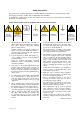
Safety Instructions This unit has been designed and tested in accordance with the EC Certificate of Conformity and has left the manufacturer’s plant in a condition fully complying with safety standards. To maintain this condition and to ensure safe operation, the user must observe all instructions and warnings given in this operating manual.
Safety Instructions Ensure that the connections with information technology equipment comply with IEC950/EN60950. 11. Lithium batteries must not be exposed to high temperatures or fire. Keep batteries away from children. If the battery is replaced improperly, there is danger of explosion. Only replace the battery by R&S type (see spare part list) Lithium batteries are suitable for environmentally-friendly disposal or specialized recycling. Dispose them into appropriate containers, only.
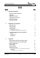
VOR/ILS Analyzer EVS200 Contents Contents Chapter 1. 2. Page Operator Information - Important operator information 1 - Unpacking 2 - Application of the unit 3 - Characteristics of the unit 4 - Unit layout frontview 5 - Unit layout rearview 6 Preparation for Operation - Placing the unit 7 - Mains operation 7 - Mains connection 7 - DC connection - 8 Assembling the FO Cable Jack Finishing and connection to the Vehicle Board Supply - Connection of Signal/Control Inputs/Outputs - 3.
VOR/ILS Analyzer EVS200 Contents Chapter Page - - - - - ILS-Mode - Operating instructions of ILS-Mode - Operating instructions of Y / t setup menu - Operating instructions of STORE DDM menu - Signal parameters on ILS Display VOR-Mode - Operating instructions of VOR-Mode - Signal parameters on VOR Display BEACON-Mode - Operating instructions of BEACON-Mode - Signal parameters on BEACON Display 16 16 17 18 20 21 21 22 23 23 24 ∆ LEVEL-Mode - Operating instructions of ∆ Level-Mode - Storing and recall
VOR/ILS Analyzer EVS200 Contents Chapter 5. Page Service - Service - Warranty 6. 55 55 Technical Specification - Technical data - General data - Accessories 0796.1800.02 56 58 59 E-8 0.
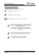
VOR/ILS Analyzer EVS200 Chapter 1: Operator Information Important operator information The symbols used in this description have the following meaning.
VOR/ILS Analyzer EVS200 Chapter 1: Operator Information Unpacking 1. Unpack the VOR/ILS Analyzer EVS200. 2. Remove the protective covers. 3. Inspect the unit for evident damage (visual check). 4. Check the auxiliary accessory! - FO-cabel jack (0018.6700.00) power cable operating instructions (0798.1988.12-07) Keep the packing material for reusing! 0796.1800.
VOR/ILS Analyzer EVS200 Chapter 1: Operator Information Application of the unit The VOR/ILS Analyzer EVS200 is used for checking terrestrial radio navigation facilities at airports.
VOR/ILS Analyzer EVS200 Chapter 1: Operator Information Characteristics of the unit Remarkable characteristics of the VOR/ILS Analyzer EVS200 are: high accuracy easy handling low power consumption very compact and light design for mobile operation battery operation (option) for mobile operation external DC operation for mobile operation remote control through RS-232-Interface selftest facillty (BITE) digital signal processing (DSP) on ILS and VOR analysys high rapidi
VOR/ILS Analyzer EVS200 Chapter 1: Operator Information Unit layout frontview LC display description battery indication (only for built-in battery (option)) mode indication bargraph center frequency indication receiver frequency bargraph indication receiver signal level squelch threshold receiver signal level signal parameters softkeys Softkeys Softkeys (program dependent functional keys) are allocated to the conforming operation mode. The softkey function is indicated on the display.
VOR/ILS Analyzer EVS200 Chapter 1: Operator Information Unit layout rearview DSP output external AF input The scaling of the XY values can be set in the setup / Y / t setup (ILS mode) for the localizer and glideslope mode. BNC socket The external AF input is to select in the setup. BNC socket 1 to 2 Vrms / 50 Ω input level: RS-232-Interface SUB-D socket: COM parameter: BAUD rate: antenna input not applicable (optional) mains switch Master switch on/off only for mains operation 0796.1800.
VOR/ILS Analyzer EVS200 Chapter 2: Preparation for Operation Preparation for operation Placing the unit The VOR/ILS Analyzer EVS200 can be operated in any position without reduction in its function. Even shocks during normal transportation or on mobile operation don’t reduce its function. The unit works at ambient temperatures of -5 to +40°C. Mains operation Safety Rules The VOR/ILS Analyzer EVS200 meets the safety rules in agreement with VDE 0411 and VDE 0804 of safety class I.
VOR/ILS Analyzer EVS200 Chapter 2: Preparation for Operation DC connection Only connect the unit when the minus pole of the battery is connected to vehicles ground (GROUND )! input voltage: 9 to 15 VDC Assembling the FO Cable Jack Finish the supplied FO cable jack (0018.6700) as following with commercial PVC cables. cable specification FO cable jack PVC wiring performance according VDE 0281 wire cross section 1.0 mm2 or more colour RED for +VDC colour BLUE for ground( ) order no.
VOR/ILS Analyzer EVS200 Chapter 2: Preparation for Operation Connection of Signal/Control Inputs/Outputs Antenna connection Via the RF INPUT at the frontside the VOR/ILS Analyzer EVS200 can be connected with a receiver antenna which agrees to frequency range. As an option a RF input at the unit’s rear side is possible. AF OUT Via the AF OUT at the frontside the demodulated AF signal will be output. AF signal bandwidth:...............................300 Hz to 4 kHz output level:.......................
VOR/ILS Analyzer EVS200 Chapter 2: Preparation for Operation External AF input Via the AF input (AF-EXT) at the rear side the unit can be fed with an AF signal for further analysis of typical AF parameters (e.g. level, frequency). This is very applicable for receivers which cannot perform AF analysis. input level: approx.: 1 to 2 Vrms / 50 Ω e.g.
VOR/ILS Analyzer EVS200 Chapter 3: Operation Operation Switch On/switch Off the unit at mains supply With the mains switch at the rearside switch the unit on or off. With the switch "POWER" at the front side switch the unit on or "STANDBY". On switch position "STANDBY" the installed battery (option) will be charged. Details see item "Battery Operation" (page 12).
VOR/ILS Analyzer EVS200 Chapter 3: Operation Selftest (BITE) The selftest checks: all operating voltages, host processor, memory, DSP processor. In case of an error the determined functional unit will be indicated with a "FAIL". If the internal operating voltages totally fail or if they deviate extraordinary from the tolerances a selftest cannot be carried out. Error: In case of an error the unit generally should be switched off and after a few seconds it schould be switched on again.
VOR/ILS Analyzer EVS200 Chapter 3: Operation Operation of the unit Because of the many universal measuring functions of the VOR/ILS Analyzer EVS200 the operation has to be carried out according to the following instructions. Basically all measurement parameter settings are realized through softkeys and the mode keys. An activated mode is shown by a luminous LED (beside the belonging mode key). All important signal parameters are analyzed by the DSP (digital signal processor) and indicated on the display.
VOR/ILS Analyzer EVS200 Chapter 3: Operation SETUP-Mode In the following table all possible parameters are listed and its functions are described. Furthermore all possible setting values per parameter are shown. Next a sequence chart of the operating instructions in the SETUP mode is following. Changes in the SETUP can be saved with the softkey "SAVE".
VOR/ILS Analyzer EVS200 Chapter 3: Operation Operating instructions of SETUP-Mode 0796.1800.
VOR/ILS Analyzer EVS200 Chapter 3: Operation ILS-Mode Operating instructions of ILS-Mode 0796.1800.
VOR/ILS Analyzer EVS200 Chapter 3: Operation Operating instructions of Y /t setup menu 0796.1800.
VOR/ILS Analyzer EVS200 Chapter 3: Operation Operating instructions of STORE DDM menu 0796.1800.
VOR/ILS Analyzer EVS200 Chapter 3: Operation 0796.1800.
VOR/ILS Analyzer EVS200 Chapter 3: Operation Signal parameters on ILS display Following signal parameters are indicated on the display: display indication DISPL 1/2 description measuring value FREQ. (MHZ) receiver frequency in MHz (numerical) and bargraph center frequency indication in kHz MHz LEVEL (dBm) receiver signal in dBm (numerical) and bargraph indication (the lower bargraph shows the set squelch threshold) dBm AM-MOD.(90HZ) AM modulation depth (90 Hz) % AM-MOD.
VOR/ILS Analyzer EVS200 Chapter 3: Operation VOR-Mode Operating instructions of VOR-Mode 0796.1800.
VOR/ILS Analyzer EVS200 Chapter 3: Operation Signal parameters on VOR display Following signal parameters are indicated on the display: DISPL 1/2 display indication description measuring value FREQ. (MHZ) receiver frequency in MHz (numerical) and bargraph center frequency indication in kHz MHz LEVEL (dBm) receiver signal in dBm (numerical) and bargraph indication (the lower bargraph shows the set squelch threshold) dBm BEARING BEARING angle DEG AM-MOD.
VOR/ILS Analyzer EVS200 Chapter 3: Operation BEACON-Mode Operating instructions of BEACON-Mode 0796.1800.
VOR/ILS Analyzer EVS200 Chapter 3: Operation Signal parameters on BEACON display Following signal parameters are indicated on the display: display indication description FREQ.
VOR/ILS Analyzer EVS200 Chapter 3: Operation ∆ Level-Mode Operating instructions of ∆ Level-Mode 0796.1800.
VOR/ILS Analyzer EVS200 Chapter 3: Operation Storing and recalling reference levels To occupy storage capacaty or to call up memory the ∆ level mode has a storage menu which will be called up by pushing the softkey "MEM". Until four memory blocks M1 to M4 can be stored or called up. Following data will be allocated to a storage space: - actual reference level, actual receiver frequency. After storing or recalling of a memory the ∆ level main window is updated with the relevant memory data.
VOR/ILS Analyzer EVS200 Chapter 3: Operation 0796.1800.
VOR/ILS Analyzer EVS200 Chapter 3: Operation Signal parameters on ∆ Level Display Following signal parameters are indicated on the display:: display indication description measuring value FREQ.
VOR/ILS Analyzer EVS200 Chapter 3: Operation Spectrum-Mode Operating instructions of Spectrum-Mode The spectrum analysis of the VOR/ILS Analyzer EVS200 is only for trend indication in the scanned range. 0796.1800.
VOR/ILS Analyzer EVS200 Chapter 3: Operation RS-232-Interface operation All important unit functions can be remote controlled via the RS-232-Interface (V24 standard) by a PC terminal which can be operated with commercial terminal programs (e.g. Telix, Procomm...). AS a data terminal (DDE) the VOR/ILS Analyzer EVS200 must be connected with a RS-232-1:1-Interface. Also it is possible to control the unit with an user defined program. The necessary commands for that purpose are described below.
VOR/ILS Analyzer EVS200 Chapter 3: Operation Unit related control commands Command RF (frequency in kHz) command function RF (frequency in kHz) setting or scanning receiving frequency With the command RF (frequency in kHz) a frequency input is possible in the ranges of 107000 to 119000 kHz and 319000 to 341000 kHz. With this command it is also possible to scan the tuned frequency when the command RF is transmitted to the EVS200 without additionally parameters.
VOR/ILS Analyzer EVS200 Chapter 3: Operation Command EC1 command function EC1 selection of communication EVS200 retransmits the received control string. Example: command from the controller response of the VOR/ILS Analyzer EVS200 EC1 ec1 query: READY READY Command test command function TEST < > RS232 test section output The command TEST initiates a RS232 test section. All ASCII characters 20h to FF will be supplied.
VOR/ILS Analyzer EVS200 Chapter 3: Operation Command RES command function RES Master-RESET With the command RES a unit master reset is possible. It works like a restart of the unit. Example: command from the controller RES res input: response of the VOR/ILS Analyzer EVS200 READY READY EVS200 REMOTE-SYSTEM READY Command BI command function BI BITE (Build In Test) -asking for result The EVS200 performs approx.
VOR/ILS Analyzer EVS200 Chapter 3: Operation Command VER command function VER query of version number and date of the EVS200 firmware The command VER initializes the display of the software version number and its issue date. Example: command from the controller VER ver query: response of the VOR/ILS Analyzer EVS200 EVS200 - VERSION < No.
VOR/ILS Analyzer EVS200 Chapter 3: Operation Command MI command function MI ILS mode setting The command MI enables the switching over to the "ILS“ mode. Example: command from the controller response of the VOR/ILS Analyzer EVS200 MI mi input: READY READY Command MB command function MB BEACON mode setting The command MB enables the switching over to the "BEACON mode“.
VOR/ILS Analyzer EVS200 Chapter 3: Operation Command DD1 command function DD1 query of the DDM value in µA The command DD1 reads the actual DDM value in µA in the ILS mode. Example: command from the controller DD1 dd1 query: response of the VOR/ILS Analyzer EVS200 e.g. e.g. 194.32uA 194.32uA Command SD0 command function SD0 SDM value query The command SD0 reads the actual SDM value (value without dimension) in the ILS mode.
VOR/ILS Analyzer EVS200 Chapter 3: Operation Command AM2 command function AM2 query of AM modulation depth (90 Hz) The command AM2 reads the actual AM modulation depth (90 Hz) in the ILS mode. Example: command from the controller AM2 am2 query: response of the VOR/ILS Analyzer EVS200 e.g. e.g.
VOR/ILS Analyzer EVS200 Chapter 3: Operation Command BW0 command function BW0 8-kHz bandwidth setting The command BW0 enables the switching over to the 8-kHz bandwidth in the ILS mode and in the "∆ ∆ level" mode.
VOR/ILS Analyzer EVS200 Chapter 3: Operation Command FA1 command function FA1 Activating the Fast DDM measurement The command FA1 switches on the fast DDM measurement. The measuring, used only for landing path measurement can only be activated through a controller. The output is performed as DDM value with RF level (see example) and can be processed accordingly with calculation programs e.g. like Excel etc.
VOR/ILS Analyzer EVS200 Chapter 3: Operation Command FA2 command function FA2 Activating the Fast DDM measurement The command FA2 switches on the fast DDM measurement. The measuring, used only for landing path measurement can only be activated through a controller.
VOR/ILS Analyzer EVS200 Chapter 3: Operation Command FA3 command function FA3 Activating the Fast DDM measurement The command FA3 switches on the fast DDM measurement. The measuring, used only for landing path measurement can only be activated through a controller. The command FA3 performs the continuous measurement and output of the DDM, RF level, Modfactor 90 Hz and Modfactor 150 Hz.
VOR/ILS Analyzer EVS200 Chapter 3: Operation Command FA0 command function FA0 deactivating the fast DDM measurement The command FA0 switches off the fast DDM measurement. Example: command from the controller response of the VOR/ILS Analyzer EVS200 FA0 fa0 input: READY READY Command D1 command function D1 switch over to display1 The command D1 enables the switching over to the content of display1 in the VOR / ILS mode.
VOR/ILS Analyzer EVS200 Chapter 3: Operation Command AF8 command function AF8 AF-frequency ID query The command AF8 reads the actual AF frequency (ID) in the ILS /VOR mode. Prediction for reading out the data of the corresponding mode (VOR/ILS) is the switching over to display2. Example: command from the controller AF8 af8 query: response of the VOR/ILS Analyzer EVS200 e.g. e.g.. 1020.0Hz 1020.
VOR/ILS Analyzer EVS200 Chapter 3: Operation VOR-Mode Command BE command funcion BE bearing angle query The command BE reads the actual bearing angle (indicated in degree) in the VOR mode. Example: command from the controller BE be query: response of the VOR/ILS Analyzer EVS200 e.g. e.g. 299.97DEG 299.
VOR/ILS Analyzer EVS200 Chapter 3: Operation Command FM0 command function FM0 FM-deviation query The command FM0 reads the actual FM-deviation value in the VOR mode. Example: command from the controller FM0 fm0 query: response of the VOR/ILS Analyzer EVS200 e.g. e.g. 479.1Hz 479.1Hz Command FM1 command function FM1 query of FM-index value The command FM1 reads the actual FM-index value in the VOR mode.
VOR/ILS Analyzer EVS200 Chapter 3: Operation Command D2 command function D2 switching over to Display2 The command D2 enables the switching over to the content of display2 in the VOR / ILS mode. This is the prediction for reading out the data of the corresponding mode (VOR/ILS).
VOR/ILS Analyzer EVS200 Chapter 3: Operation Command AM9 command function AM9 query AM-modulation depth (voice) The command AM9 reads the actual AM-modulation depth (voice 300 Hz to 3 kHz) in the ILS / VOR mode. Prediction for reading out the data of the corresponding mode (VOR/ILS) is the switching over to display2. Example: command from the controller AM9 am9 query: response of the VOR/ILS Analyzer EVS200 e.g. e.g. 09.6% 09.
VOR/ILS Analyzer EVS200 Chapter 3: Operation Command FA3 command function FA3 Activating the Fast measurement mode The command FA3 switches on the fast measurement mode. The command FA3 performs the continuous measurement and output of the RF level, Bearing, AM30, AM9960, FM-deviation, FMIndex.
VOR/ILS Analyzer EVS200 Chapter 3: Operation ∆ Level-Mode Command SR command function SR reference level setting The command SR is for setting the actual receiver level as a reference level in the reference level window "∆ ∆ level"-mode.
VOR/ILS Analyzer EVS200 Chapter 3: Operation Beacon-Mode Command AM4 command function AM4 query of AM-modulation depth (F1) The command AM4 reads the actual AM-modulation depth (F1 3000 Hz) in the BEACON mode. Example: command from the controller AM4 am4 query: response of the VOR/ILS Analyzer EVS200 e.g. e.g. 29.3% 29.
VOR/ILS Analyzer EVS200 Chapter 3: Operation Command AM7 Kommando Funktion AM6 query of AM-modulation depth ID The command AM7 reads the actual AM-modulation depth (ID) in the BEACON mode. Example: command from the controller AM7 am7 query: response of the VOR/ILS Analyzer EVS200 e.g. e.g. 10.2% 10.
VOR/ILS Analyzer EVS200 Chapter 3: Operation Command AF6 command function AF6 query of AF-frequency 400 Hz The command AF6 reads the actual AM frequency (F3) in the BEACON mode. Example: command from the controller AF6 af6 query: response of the VOR/ILS Analyzer EVS200 e.g. e.g. 400.0Hz 400.0Hz Command AF7 command Funktion AF7 query of AF-frequency ID The command AF7 reads the actual AF frequency (ID) in the BEACON mode.
VOR/ILS Analyzer EVS200 Chapter 4: Interfaces Interfaces Antenna input labeling figure description RF INPUT 50 Ω 0 dBm / 50 Ω input level: max. +15 dBm (Data safety up to 10 dBm is ensured) frequency range: 74 to 341 MHz VSWR: <1.5 AF output labeling figure description AF OUT 50 Ω output level: 200 mVrms / 50 Ω frequency range: 0.3 to 3.4 kHz Headphone connection labeling figure description Only for connecting headphones with soundproofing. PHONES e.g. R&S order no. 0708.9010.
VOR/ILS Analyzer EVS200 Chapter 4: Interfaces External AF input labeling figure description AF EXT. input level: 1 to 2 Vrms / 50 Ω frequency range: 30 Hz to 10 kHz RS-232-Interface labeling figure description standard RS-232-Interface RS232/DDE COM parameter: N81 baud rate: 1200, 2400, 4800, 9600, 19200 adjustable in the setup External VDC connection labeling figure description DC connection: tolerance max.
VOR/ILS Analyzer EVS200 Chapter 5: Service Service To ensure a unit’s repair as quick as possible a defect VOR/ILS Analyzer EVS200 must be send to the service place named in the following. In case of service questions please contact us over phone or FAX. (49) / 2203 / 49-266 (49) / 2203 / 49-336 Warranty Warranty conditions are stated in the general terms of business. Whilst time of warranty a defective internal battery (option) may only be changed by Rohde & Schwarz service personnel! 0796.1800.
VOR/ILS Analyzer EVS200 Chapter 6: Technical Specification Technical data Receiver section Frequency range Accuracy Resolution Input voltage VSWR Sensitivity IF bandwidth Demodulation RF-Input ................................ 74.7 to 75.3 MHz 107 to 119 MHz 319 to 341 MHz ................................ ≤2 ppm ................................ 5 kHz ................................ 15 dBm max./ 50 Ω (data safety up to 10 dBm is ensured) ................................ <1.5 .............................
VOR/ILS Analyzer EVS200 Chapter 6: Technical Specification Glideslope mode Measurement error at 30 to 50% modulation.......................... ≤ ±0.0008 DDM ±0.1% of reading Resolution (LOC / GS) ........................ 0.0001 DDM DSP out Localizer: Range 1 .......................... 0.0 ±25% 0 ±0.25 DDM Range 2 0.0 ±2.5% 0 ±0.025 DDM Range 3 .......................... 0.0 ±2.58% 0.0 ±0.0258 DDM Range 4 .......................... 0.0 ±50% 0.0 ±0.5 DDM Glideslope: Range 1 .......................... 0.
VOR/ILS Analyzer EVS200 Chapter 6: Technical Specification General data Power supply ................................ 100 to 240 VAC (with build-in charger) ............................... 50 to 60 Hz (440 Hz option) 9 to 15 VDC (typ. 12 VDC 1.4 A) 120 VA max. built-in battery (option) .............................. 12V / 3.2 Ah charging while mains is connected Operating time ................................ >100 min (max. brightness) >150 min (at average brightness) Mechanical resistance...............
VOR/ILS Analyzer EVS200 Chapter 6: Technical Specification Accessories Description Ident No.