
instructions and guidelines for the use of power-operated clamping devices Instruction Manual


elements, position fixing elements, point centres, etc.)
should be used exclusively for clamping those types of
workpiece for which they are designed and in the manner
intended. Failure to observe this can lead to injury or
material damage resulting from insufficient clamping
forces or unfavourable positioning. Written permission
should therefore be obtained from the manufacturer if it is
intended to clamp other / similar workpieces with the same
clamping set.
7.Checking clamping force / Clamping fixtures without
permanent application of pressure
1.Checking clamping force (general)
Static clamping force measurement fixtures must be
used in accordance with § 6.2 No. d) EN 1550 to check
the service condition at regular intervals in accordance
with the servicing instructions. Clamping force should
therefore be inspected after approx. 40 operating hours
(i.e. regardless of clamping frequency). Special clamping
force measuring jaws or fixtures (pressure measurement
cells) should be used if necessary for this purpose.
2.Clamping force check (special)
Hydraulic supplies, especially those with large line
cross--sections, involve a danger that the peak pressure
-- and with this, also the actuation force peak -- may
be considerably higher than the set pressure, due to
dynamic effects. This can lead to mechanical overloading
of the components. For this reason, during
commissioning, the actually reached total clamping force
is to be measured. The pressure may only be set to a
level where the max. total clamping force (at a standstill),
specified on the drawing or in the operating instructions,
is not exceeded.
3.Clamping fixtures without permanent application of
pressure
Clamping fixtures exist where the connection to the
hydraulic or pneumatic pressure source can be interrup-
ted during operation (e.g. for LVE / HVE). This can result
in a gradual drop in pressure. Clamping force can be
reducedsomuchasaresultthattheworkpieceisno
longer adequately clamped. Clamping pressure should
therefore be activated for at least 10 seconds every 10
minutes for safety reasons to compensate for this loss
of pressure.
This also applies after long periods of inoperation (e.g.
where machining has been interrupted overnight and
only resumed the following morning).
8.Rigidity of the workpiece to be clamped
The material to be clamped should possess a rigidity suita-
ble for the clamping force involved and should only be
minimally compressible if secure workpiece clamping
under the machining forces which occur is to be ensured.
Non--metallic material (e.g. plastic, rubber, etc.) may only
be clamped and machined with the express written
permis
sion of the manufacturer!
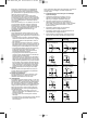
9.Clamping movements
Short distances are covered in brief periods of time under
the exertion of (at times) extreme force (e.g. through clam-
ping movements or, possibly, setup movements, etc).
It is therefore imperative that drive elements intended for
chuck actuation be deactivated in every case involving
assembly or setup work. However, if clamping movement
cannot be ruled out in setup mode and clamping distances
are greater than 4 mm
-- a fixed (or temporary) workpiece holding fixture should
be mounted on the fixture
or
-- an independently-actuated retention fixture (e.g. centring
jaws with centre chucks and face clamping chucks)
should be provided,
or
-- a workpiece loading aid (e.g. c harging stock),
or
-- setup work should be carried out in hydraulic, pneumatic
and / or electrical jogging mode (respective control should
be possible!)
The type of auxiliary setup fixture employed depends on the
machine being used and should be purchased separately if
necessary!
The machine user must ensure that every risk of injury caused
by movement of the clamping medium is ruled out during the
entire clamping procedure. 2-handed actuation for clamping
should be provided for this purpose, or, even better, suitable
safety features. The stroke monitor should be adjusted to suit
the new situation if the clamping medium is changed.
10. Manual loading and unloading
Mechanical risks to fingers in cases where clamping distances
greater than 4 mm are involved must also be taken into consi-
deration during manual loading and unloading procedures.
This danger can be countered by
-- the provision of an independently-actuated retention fixture
(e.g. centring jaws with centre chucks and face clamping
chucks),
or
-- use of a workpiece loading aid (e.g. charging stock),
or
-- a clamping movement reduction (e.g. by throttling the
hydraulic energy supply) to clamping speeds not greater than
4mms--1.
11. Fixing and replacing screws
Inferior replacements or inadequate fixing of screws which are
being changed or become loose can lead to risks of both injury
to personnel and material damage. It is therefore imperative
that, unless otherwise expressly specified, only such torque as
expressly recommended by the screw manufacturer and
suitable for the screw quality be applied when tightening
fixing screws.
The following torque table applies for the common sizes
M5 - M24 and qualities 8.8, 10.9 and 12.9:
All details in Nm
Screw quality 12.9 should be selected in cases of doubt when
replacing original screws. 12.9 quality should be selected in all
cases involving fixing screws for clamping inserts, top jaws,
fixed stops, cylinder covers and similar elements.
All fixing screws which, due to the purpose for which they are
intended, are loosened frequently and must then be tightened
again (e.g. during conversion work) should have their threads
and the bearing surface of their heads coated with a lubricating
medium every six months (grease paste).
Even securely tightened screws can become loose under
adverse outside conditions such as, for instance, vibrations.
In order to prevent this happening, all safety-related screws
(clamping fixture fastening screws, clamping set fastening
screws etc.) must be checked and, if necessary, tightened
at regular intervals.
12. Service work
Reliability of the clampingfixture canonly beensured if service
regulations in the operating instructions are followed exactly.
The following should be noted in particular:
Recommended EDS clamping force measuring system:
(external clamping only)
EDS 50 kpl. Id.-Nr. 161425
EDS 100 kpl. Id.-Nr. 161426
EDS 50/100 kpl. Id.-Nr. 161427
Quality M5 M6 M8 M10 M12 M14 M16 M18 M20 M22 M24
8.8 5,9 10,1 24,6 48 84 133 206 295 415 567 714 Nm
10.9 8,6 14,9 36,1 71 123 195 302 421 592 807 1017 Nm
12.9 10 17,4 42,2 83 144 229 354 492 692 945 1190 Nm
6
23021-k001-006_007 06.09.2006 11:14 Uhr Seite 6