
User Manual
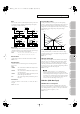
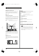

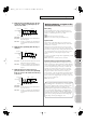

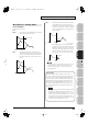

Table Of Contents
- USING THE UNIT SAFELY
- IMPORTANT NOTES
- Contents
- 01: Introduction (Overview and Basic Operation)
- 02: Sound Generator, Section 1 (Playing Sounds)
- Playing in Single Mode
- About the Single Play Screen
- Selecting a Patch
- Selecting the Tones That Will Sound (Tone On/Off)
- Playing Single Notes (Monophonic)
- Part Settings (Part View)
- Selecting the Parameter Controlled by the Realtime Controllers or D Beam Controller (Control Sett...
- Playing Percussion Instruments (Rhythm Set)
- Playing a Sample Set
- Creating a List of Frequently Used Sounds (Favorite)
- Registering a Sound (Regist)
- Recalling a Sound
- Specifying the Volume for Each Step (Favorite Level)
- Changing the Step in Which You Registered a Sound
- Removing a Sound You Registered (Remove)
- Removing All Sound Registrations from a Bank (Remove Bank)
- Registering a Song (Set Song)
- Importing a Text File (Import Text)
- Removing a Text File (Remove Text)
- Switching the Display Font (Font)
- Playing in Live Mode
- Displaying Live Play (Layer/ Split) Screen
- Functions in the Live Play (Layer/Split) Screen
- Selecting a Live Set
- Using the Live Play (Layer/ Split) Screen
- Using the Live Set Part Mixer Screen
- Using the Layer Edit Screen
- Performing with the Arpeggio
- Performing with the Realtime Controllers and D Beam Controller
- Setting Effects
- Adjusting the Master Level
- Making Detailed Settings for a Live Set
- Playing in Studio Mode
- Playing in Single Mode
- 03: Sound Generator, Section 2 (Controlling Sounds)
- 04: Sound Generator, Section 3 (Creating Sounds)
- Creating a Patch
- How to Make Patch Settings
- Saving Patches You’ve Created (Write)
- Functions of Patch Parameters
- Settings Common to the Entire Patch (General)
- Modifying Waveforms (Wave)
- Changing How a Tone Is Sounded (TMT)
- Modifying Pitch (Pitch/Pitch Env)
- Modifying the Brightness of a Sound with a Filter (TVF/TVF Env)
- Adjusting the Volume (TVA/TVA Env)
- Output
- Modulating Sounds (LFO1/2/Step LFO)
- Apply Portamento or Legato to the Sound (Solo/Porta)
- Miscellaneous Settings (Misc)
- Matrix Control Settings (Control 1–4)
- Setting Effects for a Patch (PFX)
- Creating a Rhythm Set
- How to Make Rhythm Set Settings
- Saving Rhythm Sets You’ve Created (Write)
- Functions of Rhythm Set Parameters
- Making Settings Common to the Entire Rhythm Set (General)
- Modifying Waveforms (Wave)
- Changing How a Rhythm Tone Is Sounded (WMT)
- Modifying Pitch (Pitch/Pitch Env)
- Modifying the Brightness of a Sound with a Filter (TVF/TVF Env)
- Adjusting the Volume (TVA/TVA Env)
- Output Settings (Output)
- Setting Effects for a Rhythm Set (PFX)
- Creating a Sample Set
- Creating a Live/Studio Set
- Adding Effects
- Where Effect Settings are Saved
- Turning Effects On and Off
- Making Effect Settings
- Applying Effects in Single Mode
- Applying Effects in Live Mode
- Applying Effects in Studio Mode
- Making Patch Multi-Effects Settings (PFX)
- Making Multi-Effects Settings (MFX1–2)
- Making Chorus Settings (Chorus)
- Making Reverb Settings (Reverb)
- Mastering Effect
- Effects List
- Creating a Patch
- 05: Pads (Using the Pads)
- Using the Pads
- Common Operations for Pads
- 1 SAMPLE PAD (Using the Pads to Play Samples)
- 2 RHYTHM (Using the Pads to Play a Rhythm Set)
- 3 CHORD MEMORY (Using the Pads to Switch Chord Forms)
- 4 ARPEGGIO (Using the Pads to Switch Arpeggio Styles)
- 5 RPS (Using the Pads to Play Phrases)
- 6 RHYTHM PTN (Using the Pads to Play Rhythm Patterns)
- 7 TONE SEL/SW (Using the Pads to Select Tones or Switch Them On/Off)
- 8 TRACK MUTE (Using the Pads to Mute Tracks)
- 9 BOOKMARK (Using the Pads to Recall Frequently Used Screens)
- 10 MIDI TX SW (Using the Pads to Turn External MIDI Transmit Channels (1–16) On/Off)
- 11 EFFECT SW (Using the Pads to Switch the Effects)
- 12 PATCH MFX SW (Using the Pads to Switch Patch Multi-effects)
- 13 PART SELECT (Using the Pads to Select Parts)
- 14 PART MUTE (Using the Pads to Mute Parts)
- 15 USER GROUP (Using the Pads to Register/Recall User Groups)
- 16 FAVORITE (Using the Pads to Register/Recall Favorite Settings)
- Using the Pads
- 06: Sequencer (Creating a Song)
- Playing Back a Song
- Three Ways to Play Back
- Playing a Song (Song Play)
- Loading a Song (Song List)
- Playing a Song (Song Play)
- Operations in the Song Play Screen
- Fast-forwarding or Rewinding during Playback
- Muting the Playback of a Track (MUTE)
- Accessing the Mixer Screen
- Changing the Playback Tempo of the Song
- Playing a Song Repeatedly (Loop)
- Placing Markers in a Song (Marker)
- Changing the Track Display Zoom and Display Order (Zoom/Track Order)
- Naming a Track (Track Name)
- Specifying a Track’s Output Destination (Output Assign)
- Deleting a Song File (Song Delete)
- Song Automatically Loaded at Power-on (When Loading a Project)
- Erasing the Currently-open Song (Song Clear)
- Playing a Standard MIDI File (SMF)
- Playing Phrases (MIDI Phrase)
- Recording MIDI
- Recording Audio
- Editing Songs
- Three Ways to Edit
- Editing a Song (Song Edit)
- Song Utility (Song Util)
- Editing a Phrase (Phrase Edit)
- Phrase Modify Menu
- Aligning a Phrase’s Timing (Quantize)
- Erasing Unwanted Performance Data (Erase)
- Deleting Unwanted Measures (Delete)
- Copying Phrases (Copy)
- Inserting a Blank Measure (Insert)
- Transpose the Key (Transpose)
- Changing the Velocity (Change Velocity)
- Changing the MIDI Channel (Change Channel)
- Modifying the Length of Notes (Change Duration)
- Shifting Performance Data Forward and Back (Shift Clock)
- Thinning Out the Sequencer Data (Data Thin)
- Deleting Blank Measures (Truncate)
- Editing Individual Items of Sequencer Data (Microscope)
- Saving a Song (Song Save)
- Playing Back a Song
- 07: Sampler
- Sampling
- Editing a Sample
- Selecting a Sample (Sample List)
- Displaying Sample Edit Screen (Sample Edit)
- Setting the Start/End Points of the Sample
- Making Settings for Sample (Sample Parameters)
- Removing Unwanted Portions of a Sample (Truncate)
- Boosting or Limiting the High-frequency Range of the Sample (Emphasis)
- Maximizing the Volume of a Sample (Normalize)
- Amp
- Stretching or Shrinking a Sample (Time Stretch)
- Dividing a Sample into Notes (Chop)
- Saving a Sample (Save)
- Saving all samples (Save All)
- 08: Various Settings (Menu and System)
- Menu Reference
- System Settings (Settings Common to All Modes)
- About V-LINK
- 09: Appendix

103
Creating a Patch
Overview Sound 1 Sound 2 Sound 3 Pad Sampler
Menu/System
AppendixSequencer
LFO1/2
Waveform (LFO1/LFO2 Waveform)
Selects the waveform of the LFO.
Value
SIN:
Sine wave
TRI:
Triangle wave
SAW-U:
Sawtooth wave
SAW-D:
Sawtooth wave (negative polarity)
SQR:
Square wave
RND:
Random wave
BND-U:
Once the attack of the waveform output by the LFO
is allowed to develop in standard fashion, the
waveform then continues without further change.
BND-D:
Once the decay of the waveform output by the LFO
is allowed to develop in standard fashion, the
waveform then continues without further change.
TRP:
Trapezoidal wave
S&H:
Sample & Hold wave (one time per cycle, LFO value
is changed)
CHAOS:
Chaos wave
VSIN:
Modified sine wave. The amplitude of a sine wave is
randomly varied once each cycle.
STEP:
A waveform generated by the data specified by LFO
Step 1–64. This produces stepped change with a
fixed pattern similar to a step modulator.
If you set this to “BND-U” or “BND-D,” you must turn the Key
Trigger parameter to “ON.” If this is “OFF,” it will have no
effect.
Rate (LFO1/LFO2 Rate)
★
Adjusts the modulation rate, or speed, of the LFO.
Value:
0–127, Note
LFO Rate sets the beat length for the synchronized tempo is
synchronized with the tempo set in a sequencer.
(Example)
For a tempo of 120 (120 quarter notes occur in 1 minute (60 seconds))
This setting will be ignored if the Waveform parameter is set to
“CHAOS.”
Rate Detune (LFO1/LFO2 Rate Detune)
LFO Rate Detune makes subtle changes in the LFO cycle rate (Rate
parameter) each time a key is pressed. Higher settings will cause
greater change. This parameter is invalid when Rate is set to “note.”
Value:
0–127
Offset (LFO1/LFO2 Offset)
Raises or lowers the LFO waveform relative to the central value
(pitch or cutoff frequency). Positive (+) settings will move the
waveform so that modulation will occur from the central value
upward. Negative (-) settings will move the waveform so that
modulation will occur from the central value downward.
Value:
-100, -50, 0, +50, +100
Delay Time (LFO1/LFO2 Delay Time)
Delay Time (LFO Delay Time) specifies the time elapsed before the
LFO effect is applied (the effect continues) after the key is pressed (or
released).
Value:
0–127
After referring to
“How to Apply the LFO”
(p. 104), change the
setting until the desired effect is achieved.
When using violin, wind, or certain other instrument sounds in
a performance, rather than having vibrato added immediately
after the sounds are played, it can be effective to add the vibrato
after the note is drawn out somewhat. If you set the Delay Time
in conjunction with the Pitch Depth parameter and Rate
parameter, the vibrato will be applied automatically following a
certain interval after the key is pressed. This effect is called
Delay Vibrato
.
LFO1/LFO2 Delay Time Key Follow
Adjusts the value for the Delay Time parameter depending on the
key position, relative to the C4 key (center C). To decrease the time
that elapses before the LFO effect is applied (the effect is continuous)
with each higher key that is pressed in the upper registers, select a
positive value; to increase the elapsed time, select a negative value.
Larger settings will produce greater change. If you do not want the
elapsed time before the LFO effect is applied (the effect is
continuous) to change according to the key pressed, set this to “0.”
Value:
-100, -90, -80, -70, -60, -50, -40, -30, -20, -10, 0, +10,
+20, +30, +40, +50, +60, +70, +80, +90, +100
fig.06-031.e
Setting
LFO Rate
(half note)
1 second (60 / 60 =1 (second))
(quarter note)
0.5 seconds (60 / 120= 0.5 (seconds))
(eighth note)
0.25 seconds (60 / 240= 0.25 (seconds))
C4C3C2C1 C5 C6 C7
0
+50
+100
-50
-100
Key
Time
Fantom-G_r_e.book 103 ページ 2008年1月31日 木曜日 午後12時15分