
User`s manual


Chapter 4 Appendix
44
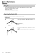
4-3 Specifications
Main Unit Specifications
The cutting range of the MDX-40 when installed with ZCL-40 rotary axis unit is as follows.
189.5 (X) x 305 (Y) x 60 (Z) mm
(7-1/2 (X) x 12 (Y) x 2-3/8 (Z) in.)
*
The range that can actually be cut is limited by the following factors.
• Amount of tool extension
• Interference between the loaded workpiece and the tool or spindle
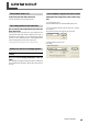
Maximum angle of rotation
Loadable workpiece size*
Workpiece thickness holdable
by workpiece chuck
Loadable workpiece weight
Control methods
Feed rate
Mechanical resolution
Rotary-axis tilt angle
Dimensions
Weight
Packed dimensions
Packed weight
Accessories
ZCL-40
±18x10
5
˚ (± 5000 rotations)
Items within the range of a 42.5 mm (1-11/16 in.) radius from the center of the rotary
axis by long 135 mm (5-3/8 in.)
12 to 40 mm (1/2 to 1-5/8 in.)
0.5 Kg (1.1 lb)
(Maximum workpiece moment of inertia 6x10
-4
kgm
2
)
4-axis control (3-axis simultaneous control)
11.79 rpm
0.0225 deg.
0 deg. to 90 deg. (in increments of 15 deg.)
357 (W) x 305 (D) x 129 (H) mm
(14-1/16 (W) x 12 (D) x 5-1/8 (H) in.)
6.2 Kg (13.7 lb)
490 (W) x 440 (D) x 260 (H) mm
(19-3/8 (W) x 17-3/8 (D) x 10-1/4 (H) in.)
9 Kg (20 lb)
Y-origin sensors (large and small), Z-origin sensor, Y-origin detection pin, center drill,
live center, hexagonal wrench, cap screws (for securing Z-origin sensor), user's manual