
User`s manual


45
Part 2
<R>
Rating plate......................................................................... v
REPEAT”.................................................................... 21, 24
Repeat cutting ................................................................... 21
Replacing the motor brushes ............................................ 27
“RESOLUTION” ............................................................. 26
Revolution speed .................................................. 13, 14, 15
“REVOLUTION TIME” ............................................ 26, 29
“REVOLUTION” ............................................................. 26
RPM.................................................................................. 14
RS-232C ................................................................... 5, 6, 42
<S>
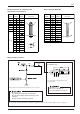
Scale (for checking the Z-axis cutting range)..................... 2
Scale (for checking the Z1 position) .................................. 2
“SERI” .............................................................................. 25
Serial cable ......................................................................... 5
Serial connection ............................................................ 5, 6
Serial connector .................................................................. 2
Smoothing......................................................................... 26
“SMOOTHING”............................................................... 26
Specifications ................................................................... 42
Spindle control.............................................................. 3, 14
“SPINDLE LOCK” .......................................................... 33
Spindle motor ................................................................... 28
Spindle motor revolution speed ............................ 13, 14, 15
Spindle rotation time ........................................................ 29
SPINDLE TEST ON/OFF key ........................................... 3
“STOP” (I/O) ................................................................ 6, 25
“STOP” (pause state) ........................................................ 23
Stop bits ........................................................................ 6, 25
Symbols ............................................................................ iii
<T>
Table ................................................................................... 2
Table size .......................................................................... 42
Terminator ........................................................................ 37
Thickness of materials ....................................................... 7
“TOO BIG DATA” ........................................................... 33
Trouble shooting............................................................... 30
<V>
Vacuum adaptor ............................................................ 1, 11
“VIEW” ............................................................................ 24
<W>
Workpiece ........................................................................... 7
Wrenches .................................................................... 1, 7, 8
<X>
X-axis ............................................................................... 19
“XY-SPEED”.............................................................. 13, 24
<Y>
Y-axis ................................................................................ 19
<Z>
Z-axis ................................................................................ 19
“Z-SPEED”................................................................. 13, 24
“Z0” .................................................................................. 24
“Z0/Z1/Z2 MEMORY” .................................................... 26
Z0 position ........................................................................ 11
“Z1” .................................................................................. 24
Z1 position ........................................................................ 16
“Z2” .................................................................................. 24
Z2 position ........................................................................ 16
Z adjust screw ........................................................... 2, 9, 10
-Z key.................................................................................. 3
+Z key................................................................................. 3