Thank you very much for purchasing the GX-500/400/300. • To ensure correct and safe usage with a full understanding of this product's performance, please be sure to read through this manual completely and store it in a safe location. • Unauthorized copying or transferral, in whole or in part, of this manual is prohibited. • The contents of this operation manual and the specifications of this product are subject to change without notice.
For the USA NOTICE FEDERAL COMMUNICATIONS COMMISSION RADIO FREQUENCY INTERFERENCE STATEMENT Grounding Instructions Do not modify the plug provided - if it will not fit the outlet, have the proper outlet installed by a qualified electrician. This equipment has been tested and found to comply with the limits for a Class A digital device, pursuant to Part 15 of the FCC Rules.
Table of Contents To Ensure Safe Use ................................................................................................................... 2 Pour utiliser en toute sécurité ................................................................................................. 8 Important Notes on Handling and Use ....................................................................................... 13 1 Checking Supplied Items ........................................................................
To Ensure Safe Use Improper handling or operation of this machine may result in injury or damage to property. Points which must be observed to prevent such injury or damage are described as follows. About WARNING and WARNING CAUTION Notices Used for instructions intended to alert the user to the risk of death or severe injury should the unit be used improperly. Used for instructions intended to alert the user to the risk of injury or material damage should the unit be used improperly.
To Ensure Safe Use Incorrect operation may cause injury WARNING CAUTION Be sure to follow the operation procedures described in this documentation. Never allow anyone unfamiliar with the usage or handling of the machine to touch it. Incorrect usage or handling may lead to an accident. Keep children away from the machine. The machine includes areas and components that pose a hazard to children and may result in injury, blindness, choking, or other serious accident.
To Ensure Safe Use Danger of electrical short, shock, electrocution, or fire WARNING Connect to an electrical outlet that complies with this machine's ratings (for voltage, frequency, and current). Incorrect voltage or insufficient current may cause fire or electrical shock. Ratings WARNING Handle the power cord, plug, and electrical outlet correctly and with care. Never use any article that is damaged. Using a damaged article may result in fire or electrical shock.
To Ensure Safe Use Important notes about the power cord, plug, and electrical outlet Never place any object on top or subject to damage. Never allow to get wet. Never bend or twist with undue force. Never make hot. Never pull with undue force. Dust may cause fire. Never bundle, bind, or roll up.
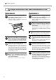
To Ensure Safe Use Warning Labels Warning labels are affixed to make areas of danger immediately clear. The meanings of these labels are as follows. Be sure to heed their warnings. Also, never remove the labels or allow them to become obscured. Caution: Moving Carriage The cutting carriage moves at high speed and pose a hazard. Keep your hands away from it. Caution: Entanglement Hazard Never inadvertently allow hands, hair, clothing such as neckties, or the like near rotating parts while in operation.
To Ensure Safe Use 7
Pour utiliser en toute sécurité La manipulation ou l'utilisation inadéquates de cet appareil peuvent causer des blessures ou des dommages matériels. Les précautions à prendre pour prévenir les blessures ou les dommages sont décrites ci-dessous. Avis sur les avertissements ATTENTION Utilisé pour avertir l'utilisateur d'un risque de décès ou de blessure grave en cas de mauvaise utilisation de l'appareil.
Pour utiliser en toute sécurité L'utilisation incorrecte peut causer des blessures ATTENTION S'assurer de suivre les procédures d'utilisation décrites dans la documentation. Ne jamais permettre à quiconque ne connaît pas le fonctionnement ou la manutention de l’appareil de le toucher. L'utilisation ou la manutention incorrectes peuvent causer un accident. Garder les enfants loin de l'appareil.
Pour utiliser en toute sécurité Risque de décharge ou de choc électrique, d'électrocution ou d'incendie ATTENTION Brancher à une prise électrique conforme aux caractéristiques de cet appareil (tension, fréquence et courant). Une tension incorrecte ou un courant insuffisant peuvent causer un incendie ou un choc électrique. Caractéristiques ATTENTION Manipuler le câble d'alimentation, la fiche et la prise électrique correctement et avec soin.
Pour utiliser en toute sécurité Remarques importantes à propos du câble d'alimentation, de la fiche et de la prise électrique Ne jamais déposer aucun objet sur le câble, sur la fiche ou sur la prise car cela risque de les endommager. Ne jamais laisser l'eau toucher le câble, la fiche ou la prise. Ne jamais plier ni tordre le câble avec une force excessive. Ne jamais chauffer le câble, la fiche ou la prise. Ne jamais tirer sur le câble ou la fiche avec une force excessive.
Pour utiliser en toute sécurité Vignettes d'avertissement Des vignettes d'avertissement sont apposées pour qu'il soit facile de repérer les zones dangereuses. La signification des vignettes est donnée ci-dessous. Respecter les avertissements. Ne jamais retirer les vignettes et ne pas les laisser s'encrasser. Attention : Chariot mobile Le chariot de coupe se déplace très rapidement et peut être dangereux. Tenir les mains loin du chariot.
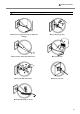
Important Notes on Handling and Use This machine is a precision device. To ensure the full performance of this machine, be sure to observe the following important points. Failure to observe them may not only result in loss of performance, but may also cause malfunction or breakdown. Main unit This Machine Is a Precision Device ➢Handle carefully, and never subject the machine to impact or excessive force.
14
1 Checking Supplied Items Check the following to make sure that you received all the items that were shipped along with the unit. Blade holder (XD-CH2) Power cord 2 Pin Replacement blade for separating knife Cable clamp Setup Guide User’s Manual (this document) Blade Alignment tool CD-ROM (Roland Software Package) USB cable Part Names and Functions 2-1 Front View * The figure shows the GX-500 installed with the PNS-502 special stand.
2-2 Rear View Power Connector Connect the power cord included with the machine to this connector. Sheet Loading Lever These raise and lower the pinch rollers. USB Connector This is for connecting a computer with a USB cable. Tray Use this to store blades. Sheet Sensor Brake Serial Connector This is for connecting a computer with a serial cable. 2-3 Operation Panel For more information about the keys, see the respective reference sections and “6-3 List of Functions.
3 Basic Operation 3-1 Loading the Material (Roll Material) Roll material must be placed at a predetermined shaft position. Failure to do so may result in falling of the roll, leading to injury. Acceptable Material Width and Maximum Cutting Width Acceptable material widths Maximum cutting width GX-500 Min.90 mm (3-1/2 in.) Max.1372 mm (54 in.) 1195 mm (47 in.) GX-400 Min.90 mm (3-1/2 in.) Max.1178 mm (46 in.) 1000 mm (39 in.) GX-300 Min.50 mm (2 in.) Max.915 mm (36 in.) 737 mm (29 in.
Loading Roll Material * When performing lengthy cutting of 1.5 m (60 in.) or more, please refer to the section “4-3 To Perform Lengthy Cutting”. For information on how to install the sheet hangers, shafts, brake, and stoppers, please refer to the “ASSEMBLY INSTRUCTIONS” for the PNS-502/402/302 (the stand for the GX-500/400/300). 1 Mount the shafts on the sheet hangers to match the outer diameter of the roll material. If mounted at an incorrect position, the roll may fall off.
4 Using the grit marks as a reference, position the material so that its right edge lies over the right grit roller and its left edge simultaneously lies over any of the other grit rollers. Grit marks These indicate the position of the grit rollers. Grit rollers Grit roller (Right) Material Sensor Load the material so that it lies over the sensor on the platen.
GX-400 Material Loading Position : Grit Roller : Movable Pinch Roller (Middle) : Movable Pinch Roller (Left) : Movable Pinch Roller (Right) 6 in.(approx. 152 mm) 12 in. (approx. 305 mm) Material 18 in. (approx. 457 mm) 24 in. (approx. 610 mm) 30 in. (approx. 762 mm) 36 in. (approx. 914 mm) 46 in. (approx. 1178 mm) The right-hand movable pinch roller can be moved within this range. When loading material with a width other than one indicated above, move the right-hand movable pinch roller.
GX-300 : Grit Roller Material Loading Position : Movable Pinch Roller (Left) : Movable Pinch Roller (Right) 6 in.(approx. 152 mm) 12 in. (approx. 305 mm) Material 18 in. (approx. 457 mm) 24 in. (approx. 610 mm) 30 in. (approx. 762 mm) The right-hand movable pinch roller can be moved within this range. When loading material with a width other than one indicated above, move the right-hand movable pinch roller. * Acceptable material widths 50 to 540 mm (2 in. to 21 in.), 582 to 915 mm (23 in.
5 Pull out material toward the front, position it in place so that it is lined up straight with the guide lines, then move the left and right pinch rollers to position them above the grit rollers. Position the middle pinch roller at the center between the left and right pinch rollers. If a grit mark is present between the left and right pinch rollers, position the middle pinch roller above the corresponding grit roller.
8 Switch on the power. 9 At [SELECT SHEET], use the [ ] and [ ] keys to select [ROLL], then press the [ENTER] key. For more information about selecting material, see “42 Details of the Origin-point Location and Cutting Area.” SELECT SHEET *ROLL 10 The SETUP LED lights up (setup state), and the horizontal width of the material is detected and shown on the display. Setup is now complete.
3 Insert the blade. Blade Holder Blade 4 (1) Loosen the tool securing screw on the tool carriage. (2) Support the tool securing screw from below and install the blade holder. Insert the blade holder until the collar is flush with the carriage. (3) Tighten the tool securing screw until the blade holder is secured in place. Tool carriage Tighten Loosen Tool securing screw When you're using general sign material, use with the cap tightened all the way to the top (maximum amount of blade extension: 2.
3 Check the state of cutting. (1) Peel off the round section (marked by ). When it can be peeled by itself, without disturbing the square (marked by ), the blade force is set appropriately. (2) Remove the square section (marked by ). The optimum blade pressure is correct if you can clearly make out the lines left by the blade. For Materials with a Strong Adhesive Layer If you are using a material with a strong adhesive layer, the adhesive layer may adhere to itself immediately when cut.
Adjusting the Cutting Speed Examine the results of the cutting test and adjust the cutting speed accordingly. 1 Press the [SPEED] key to display the screen in the figure. SPEED 20cm/s *20cm/s Cutting-speed adjustment Setting range: 1 to 85 cm/s (settable in increments of 1 cm/s) 2 Use the [ ] and [ ] keys to adjust the value, then press the [ENTER] key to enable the setting. Incorrect cutting conditions may cause symptoms such as those described below.
3-5 Starting Cutting Material Test Feed Perform test feed beforehand to ensure that the roll material is not pulled with undue force during cutting. If the roll material is pulled with undue force during cutting, a motor error may occur, or the position may be displaced. Test feed can also be performed to make sure that the loaded material is straight. Using the [AREA] feature makes it simple to perform test feed for the required portion.
Downloading Cutting Data Cutting starts when the machine receives cutting data sent from the computer. NOTICE If the material becomes dislodged or there is a problem in operation, then immediately press the [PAUSE] key or turn off the power switch on the right side of the machine. The CAMM-1 driver is necessary to perform cutting with this machine using data created by another program. The CAMM-1 driver is found on the included CD-ROM.
To Change the Cutting Speed or Blade Force During Cutting If you change the cutting speed or blade force during cutting, carry out the operation described below. 1 Press the [PAUSE] key. The cutting operation pauses and the screen shown in the figure appears. CONTINUE STOP 2 If you want to change the cutting speed, press the [SPEED] key. If you want to change the blade force, press the [FORCE] key.
3-6 When Cutting is Completed When not in use for extended periods, unplug the power cord from the electrical outlet. Failure to do so may result in danger of shock, electrocution, or fire due to deterioration of the electrical insulation. NOTICE Never leave the tool securing screw tightened. Tightening the screw makes it more difficult to install the blade holder. Never leave the machine with the pinch rollers lowered. The rollers may deform, making normal material feed impossible.
4 Advanced Operation 4-1 Detailed Cutting-condition Settings Adjusting the Blade Extension When you want to perform accurate and fine adjustment of the cutting-in amount, such as when cutting material with thin carrier paper or when performing half-cutting of material having no carrier paper, you can obtain good results by adjusting the tip of the blade. Each indicator tick corresponds to 0.1 mm, and adjustment for 0.5 mm can be made by rotating the cap one full turn.
2 Press the [ Press the [ ] key. ] key. FORCE 50gf 3 4 Press the [ ] several times. OFFSET 0.250mm Press the [ ] key. Use the [ ] and [ ] key to set the value. OFFSET 0.250mm *0.275mm Blade-offset adjustment Setting range: 0 to 1.000 mm (in increments of 0.025 mm) 5 Press the [ENTER] key to enable the value. Press the [MENU] key to go back to the screen shown in the figure. 20cm/s 50gf 0.
3 Press the [ 4 Press the [ ] key. Use the [ ] and [ ] keys to enter the up speed. ] key several times. UPSPEED AUTO UPSPEED AUTO *50cm/s Adjusting the Up Speed Setting range: AUTO, 10 to 50 cm/s (in increments of 10 cm/s) 5 Press the [ENTER] key to enable the up speed. Press the [MENU] key to go back to the screen shown in the figure. 20cm/s 50gf 0.250mm A Settings for Cutting Quality You can select whether speed is given priority in cutting, or whether cutting quality is emphasized.
4-2 Details of the Origin-point Location and Cutting Area The Location of the Origin Point Immediately After Loading Material With this machine, the initial origin point is determined when you load material and press the [ENTER] key. This origin point differs according to the selection made for [SELECT SHEET] on the operation panel when loading material.
The Location of the Origin Point Immediately After Loading Material (When [ROTATE] is set to [0deg]) “ROLL” (When using roll material) The origin point is set at the location where the material is loaded, near the left pinch roller. Material Pinch Roller (0.0) Margin Depends on length when loaded “F-EDGE” (When performing cutting from as close as possible to the front edge of the material) Material Pinch Roller Set the origin point at a location having a margin of 30 mm (1-3/16 in.
Coordinate Rotation Settings This rotates the cutting coordinates by 90 degrees. The default setting is at [0deg], and the origin point is set at the lower left of the material. Setting this to [90deg] set the origin point at the lower right of the material and rotates the text (or graphics) by 90 degrees. * Note that the coordinate axes change when rotated. Make the settings to match the program you're using.
About the Cutting Area The cutting area along the horizontal plane (the direction in which the tool carriage moves) is determined by the position of the pinch rollers. The workable area spans the length between the two rollers, minus a margin of about 1 mm (about 0.04 in.) on both sides. If the material length is greater than 1,600 mm (63 in.) when a flat material has been loaded, this machine determines it to be a roll material and sets the material length to 24,998 mm (984-1/8 in.).
2 Pull out the material from the roll and pass it through the unit. Stretch taut, with no slackness. 3 Position the left and right pinch rollers as shown in the figure, and position the middle pinch roller at the center between the left and right pinch rollers. If a grit mark is present between the left and right pinch rollers, position the middle pinch roller above the corresponding grit roller. Pinch roller (middle) Pinch roller (left) 25 mm (1 in.) or more Guide lines 25 mm (1 in.
7 Use the operation panel as follows to perform test feed for the material. The material is fed out by the set length. Make sure the material is not crooked. If the material is crooked and looks like it might come loose from the pinch rollers, press the [PAUSE] key, then hold down the [ENTER] key for 0.5 seconds or longer to stop material feed. Reload the material. SELECT SHEET *ROLL Use [ ] or [ ] to select [ROLL]. Press [ENTER]. W:500mm L:----Press [MENU] twice. Press [ ]. Press [ ].
If a pinch roller is positioned over an area where there is no grit roller, the message shown in the figure appears when you press the [ENTER] key. If this occurs, lower the sheet loading levers and move the pinch rollers to the proper positions above the grit rollers. Reposition the material to match this new alignment, then lift the sheet loading levers to hold the material in place.
4-6 Front Loading You can use the front-loading feature of this machine, which lets you load roll material at the front of the machine, by installing the sheet hangers on the front. Installing the Sheet Hangers Install the sheet hangers on the front of the machine. For an explanation of how assemble the unit and the stand (PNS-502/402/302), refer to the “ASSEMBLY INSTRUCTIONS” included with the stand. Loading Material 1 Refer to “3-1 Loading the Material (Roll Material)” and load the material.
About the Origin Point and the Cuttable Area For front loading, the [SELECT SHEET] setting made when you load the material must be set to either [ROLL] or [R-EDGE]. The origin-point location and the area where cutting is possible are as shown below. (The figure shows the case where [ROTATE] is set to [0 deg].) [R-EDGE] Set at the inner left edge of the material [ROLL] Set near the left-hand pinch roller 30 mm (1-3/16 in.) Cutting area Depends on length when loaded No cutting area (0.
6 Press the [MENU] key to back to the screen shown in the figure. If the material is crooked and looks like it might come loose from the pinch rollers, or actually does come loose, reload the material. 20cm/s 50gf 0.250mm A In addition to the preceding method, you can also set the origin point by using the [ ] and [ required length of material to the rear of the machine, then pressing the [ORIGIN] key. For more information, see “3-4 Setting the Origin Point.
4-7 The Overcut Feature This cuts an excess margin of 1 mm (0.04 in.) from the first and last line segments. This is effective when you want to finish with angles that are especially sharp, such as when cutting thick material. This should normally be left set at [DISABLE]. When you want to cut especially attractive corners, set it to [ENABLE].
4-8 The Memory Feature With this machine, you can set and store eight types of cutting conditions for different tools and materials. You can call up the settings simply by using the [MEMORY] key. To Store in Memory 1 Use the display menu to make the settings for cutting conditions matched to the tool and material in use. You can set the following five types of parameters.
Calling Up 1 Press the [MEMORY] key. 2 Use the [ ] and [ ] keys to select the user number you want to call up. The parameters set to the selected user number appear on the display. 3 Press the [ENTER] key. The user number you selected is called up and the display changes as shown in the figure. LOAD *USER1 20-50-0.250 Speed - Force - Offset 20cm/s 50gf 0.250mm A Deleting Settings You can delete the stored settings for cutting conditions, returning them to their factory defaults.
4-9 The Crop Mark Feature Use this feature when you create stickers or the like with data created by a program in which printing data and cutting data are interlocked, cut around figures that are already printed on the material. Crop marks are the marks used for alignment when cutting the printed material on the cutting machine. Saving on the machine the locations of the crop marks oriented together with the image makes it possible to adjust the location to cut.
2. Get ready to perform cutting. When you have completed the figure data containing crop marks, print the material. Load the material (printed with a figure), and install the included alignment tool (see “3-1 Loading the Material,” “3-2 Installing a Blade,” and “4-4 Loading Flat Material (Standard-size Material, Piece Material, Etc.)”). The way of installing the alignment tool is the same as for the blade holder. 3. Select the operation mode and enter the setting values.
4. Perform cutting. First use the alignment tool to line up the tip of the alignment tool with the leading edge of the crop marks, then send the cutting data. 1 Press the [ ] key. Use the [ ] and [ ] keys to select either [4-POINT START] or [3-POINT START], then press the [ENTER] key. For four crop marks, select [4-POINT START]. For three crop marks, select [3-POINT START]. The screen shown in the figure appears.
9 Press the [ENTER] key The screen shown in the figure appears. When you've finished making the settings, then to perform cutting, press the [ENTER] key. * Pressing the [MENU] key cancels the settings and returns you to the screen shown in the figure. 10 Make sure that the screen shown in the figure flashes, then send the data from the computer. Cutting starts when the data is received. When cutting finishes, the screen shown in the figure appears. COMPLETED STOP ENTER MENU 20cm/s 50gf 0.
5 About the Blades and Materials 5-1 Blade and Material Combinations This section indicates the proper cutting conditions for various types of materials, as well as blade life-span. Cutting conditions and blade life vary according to the hardness of the material and the usage environment. Making the settings for the conditions described below does not automatically guarantee attractive cutting results in all situations.
5-2 About Special Materials [Rubber materials for sandblasting stencils which can be cut] A) Materials with a material thickness of 1 mm (0.04 in.) or less B) Materials with only carrier paper on both flanks of the material (Position the left and right pinch rollers above the strips of carrier paper.) C) Materials with carrier paper which is hard enough to withstand material feed Material Carrier paper A) 1 mm (0.04 in.) or less B) 15 mm (5/8 in.) or more B) 15 mm (5/8 in.
6 Descriptions of Features 6-1 Key Operations This describes the key operations. Refer to this together with the display-menu flowcharts on the following pages to make settings using the menus. Direct Keys [MEMORY] [FORCE] [SPEED] Pressing any one of these three keys displays the setting screen. Use [ ] and [ ] to change the setting value, then press [ENTER] to enable the setting. * If you press another key without pressing [ENTER], the setting value does not change.
6-2 Display Menus Flowchart For details about each of the menus, see “6-3 List of Functions.” Power ON GX-500 Roland DG Corp. Select sheet SELECT SHEET * ROLL < ROLL, F-EDGE, R-EDGE, PIECE > ENTER NOW LOADING • • • • • Width and length of cutting area W : 1195mm L : ------ to [MEMORY] MENU MENU Present cutting condition 20cm/s 50gf 0.250mm MENU UNSETUP A to [QUALITY] CONDITION FORCE 50gf FORCE 50gf * 50gf SPEED 40cm/s SPEED 20cm/s * 20cm/s OFFSET 0.250mm OFFSET 0.250mm * 0.
Continue Continue Only when the [AUTO / SERIAL] is selected, it is possible to set. to [HAND] I/O < AUTO > I/O AUTO * AUTO BAUD 9600 BAUD 9600 * 9600 DATA 8 DATA 8 *8 STOP 1 STOP 1 *1 PARITY NONE PARITY NONE NONE HAND. H-WIRE HAND.
Continue Continue to [CALIB] OTHERS SMOOTHING ON SMOOTHING ON * ON UNIT mm UNIT mm * mm FACTORYDEFAULT FACTORYDEFAULT * PRESET SELF TEST CONTRAST 5 CONTRAST 5 *5 TEST PATTERN TYPE 1 TEST PATTERN TYPE 1 * TYPE 1 OVER CUT DISABLE OVER CUT DISABLE * DISABLE to [CALIB Y] CALIB to [SMOOTHING] CALIB X 0.00% CALIB X 0.00% * 0.00% CALIB Y 0.00% CALIB Y 0.00% * 0.
6-3 List of Functions Control-key Functions This describes the functions of the control keys when pressed. Key MEMORY Function Range Default This calls up user-set cutting conditions matched to the USER1 to 8 – This sets the force for the blade during cutting. 20 to 350 gf 50 gf Perform a cutting test and set the conditions to match (10 gf step) tool and material in use. FORCE the loaded material and the installed blade. SPEED This sets the speed for the blade during cutting.
Description of Menu Items This describes the items and functions available when you press [MENU] and enter the menu mode. Menu UNSETUP CONDITION FORCE SPEED OFFSET UPSPEED ROTATE AREA QUALITY CROPMARK 58 Function Range Default This cancels material setup (unsetup). This sets the force of the blade when the material is cut. Make the setting suitable for the material and the blade installed in consideration of the result of the cutting test.
Menu I/O BAUD DATA STOP PARITY HAND AUTOCUT SPEED MARGIN PASSES COMMAND Function Range This makes the setting for the type of interface used AUTO/ for connection to the computer. This is normally set to USB/ [AUTO]. SERIAL This machine cannot use two ports concurrently. When set to [AUTO], the first port that receives data after the power is turned on is selected as the usable port. To use the other port, either reset the power or change the interface setting using this menu item.
Menu Function Range SETTING VS CMD COMMANDS OTHERS To perform cutting at the speed determined by a VS DISABLE/ENABLE command (tool speed setting command) sent from the computer, set this to [ENABLE]. When set to [DISABLE], cutting is performed using the values for [**cm/s] at the cutting conditions screen and [UPSPEED]. !FS CMD To perform cutting at the blade force determined by an DISABLE/ENABLE FS command (tool force setting command) sent from the computer, set this to [ENABLE].
Menu OVER CUT CALIB REPLOT MEMORY Function Range This cuts an excess margin of 1 mm (0.04 in.) from the DISABLE/ENABLE first and last line segments. This selection is normally set to [DISABLE], and is set to [ENABLE] when cutting especially attractive corners is desired. When cutting small text or intricate graphics, however, this should be set to [DISABLE] to avoid cutting the text or graphics portion of material. This adjusts the respective distances of the X axis and -2.00 to 2.00 % Y axis.
62
7 Maintenance 7-1 Cleaning NOTICE Always turn off this machine before cleaning it. Never lubricate the mechanisms. Do not clean with solvents (such as benzine or thinner). [Cleaning the body] Use a cloth moistened with water then wrung well, and wipe gently to clean. Wipe the operation panel and display gently with a clean, soft cloth. [Cleaning the platen] Use a cloth moistened with water then wrung well, and wipe gently to clean.
7-2 Consumable Items [Blade] If any of the following occurs, it means the blade has reached the end of its useful life. Replace with a new blade. • The blade tip is broken. • Uncut areas remain even when blade force is raised 50 to 60 gf. • Cutting traces are not as attractive as they were previously. • When cutting details or corners, the material layer peels away from the carrier paper.
7-3 How to Replace the Separating Knife Make sure the power to the unit is off before attempting to replace the separating knife. Doing so may result in injury. If the separating knife is not sharp enough to cut attractively, replace it with the replacement knife included with this machine. Follow the steps below to replace the knife. 1 Switch off the power to the machine. 2 Remove the separating knife. (1) Loosen the screw until it slips out.
66
8 If There Is a Problem 8-1 Self-test Operation Check This machine is provided with a self-test feature for verifying that operation is correct. If this machine does not operate correctly, follow the steps below to check its operation. (No computer is required to perform an operation check.) 1 Refer to “3-1 Loading the Material (Roll Material)” and load material. 2 Refer to “3-2 Installing a Blade” and install the blade holder in the tool carriage. 3 Press the [MENU] key several times.
8-2 What to do if... GX-500/400/300 Troubleshooting Is the power cord connected correctly? Connect the power cord bundled to the machine, and plug the other end securely into an electrical outlet. Is the machine power on ? Turn on the power. Is the machine in the temporary halt state ? Is operation paused? If the screen shown in the figure is displayed, CONTINUE PAUSE it means that operation is paused. STOP ENTER To resume cutting, press the [PAUSE] key again.
A message appears on the display BAD POSITION SHEET UNLOADED MOTOR ERROR TOOL-CHG:TOOL No The location of one or more of the pinch rollers is not correct. Press the [ENTER] key to clear the error, then reload the material correctly. (Refer to “3-1 Loading the Material (Roll Material).”) This is displayed when the material has been loaded at a position where the sheet sensor does not function.
Cut lines are uneven or not cut attractively Are the blade and blade holder installed correctly and securely ? Install them tightly enough not to loose (see “3-2 Installing a Blade.” ) Are there material debris in the blade holder? Remove the cap from the blade holder and clean out the debris. (Refer to “7-1 Cleaning.”) Is a thick material being used? When you are using thick material, set the [QUALITY] to [HEAVY]. (Refer to “41 Detailed Cutting-condition Settings.
Blank areas are produced on the material Are the blank areas due to the specifications? Mechanical limitations produce margins at the front, back, left, and right of the material. (Refer to “4-2 Details of the Origin-point Location and Cutting Area.”) Flat material cannot be set up as “PIECE” (the length is not displayed) Is the length 1.6 m (63 in.) or longer? Attempting to set up flat material having a length of 1.6 m or longer as [PIECE] causes the material to be recognized as roll material.
8-3 Error Messages An error message will appear if incoming data has any of the errors listed in table. However, the error is shown in the display for informational purposes, the data transfer continues and you are allowed to perform the next operation. To clear the display, press any key. If an error occurs, correct cutting may become impossible. The error messages that may appear on the display are described below. In almost all cases, the cause is receiving incorrect data.
9 Specifications 9-1 Locations of the Power Rating and Serial Number Labels Serial Number This is required when you seek maintenance, servicing, or support. Never peel off the label or let it get dirty. Power Rating Use an electrical outlet that meets the requirements for voltage, frequency, and amperage given here.
9-2 Specifications GX-500 Mechanism Media-movement method Driving method Digital control servo motor Maximum cutting area Acceptable media widths GX-300 GX-400 Width: 1195 mm (47 in.) Width: 1000 mm (39 in.) Width: 737 mm (29 in.) Length: 24998 mm (984-1/8 in.) Length: 24998 mm (984-1/8 in.) Length: 24998 mm (984-1/8 in.) Min. 90 mm (3-1/2 in.) / Min. 90 mm (3-1/2 in.) / Min. 50 mm (2 in.)/ Max. 915 mm (36 in.) Max. 1372 mm (54 in.) Max. 1178 mm (46 in.) (50 to 540 mm (2 in. to 21 in.
( *1) The following conditions must be satisfied: • Material type: 3M Scotchcal Mastercut • Special stand (a roll material must be set at the rear and on the sheet hanger) • Side margins: 25 mm (1 in.) or more for both the left and right margins • Front margin: 30 mm (1-3/16 in.) or more (After loading the material, using the display menu to select [F-EDGE] as the material type automatically sets a front margin of 30 mm (1-3/16 in.).
9-3 Interface Specifications [Serial] Standard Transmission method Transmission speed Parity check Data bits Stop bits Handshake RS-232C specifications Asynchronous, duplex data transmission 4800, 9600 (Selected using panel keys.) Odd, Even, or None (Selected using panel keys.) 7 or 8 bits (Selected using panel keys.) 1 or 2 bits (Selected using panel keys.) Hardwire (power on) or XON/XOFF (Selected using panel keys.) [USB] Standard Universal Serial Bus Specification Revision 1.
R1-060421