
Specifications


24
Blade Holder
Blade
Tool carriage
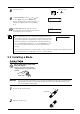
Loosen
Tool securing screw
Tighten
3
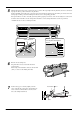
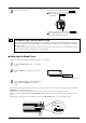
Insert the blade.
4
(1) Loosen the tool securing screw on the tool
carriage.
(2) Support the tool securing screw from below and
install the blade holder. Insert the blade holder
until the collar is flush with the carriage.
(3) Tighten the tool securing screw until the blade
holder is secured in place.
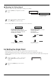
When you're using general sign material, use with the cap tightened all the way to the top (maximum amount of blade
extension: 2.5 mm). When cutting material whose carrier paper is thin with respect to the adhesive layer (that is, the
material thickness), or when performing half-cutting for material with no carrier paper, adjust the blade tip so that the tip
does not pierce the carrier paper. For more information, see “4-1 Detailed Cutting-condition Settings.”
3-3 Adjusting the Blade Force and Cutting Speed
Before you perform the actual cutting, carry out a cutting test to check the cutting quality for the material. Examine the result of the
cutting test, adjust the value of the blade force and cutting speed.
Repeat the procedure described below until the appropriate cutting conditions for the material in use are discovered.
Cutting Test
1
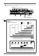
Use the [ ], [ ], [ ] and [ ] keys to move
the tool carriage to the place where the cutting test is
to be performed.
• Note that an area of approximately 2 square
centimeters (a little less than a square inch) is
required to make a test cutout (given that the tip
of the blade after it has moved is at the origin at
lower-left).
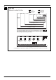
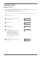
2
Hold down the [TEST] key for 0.5 seconds or longer.
Cutting test starts.
(Position of the tip of
the blade installed in
step 1)
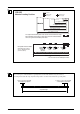
A cutting test is not possible immediately after you have chosen [R-EDGE] at [SELECT SHEET]. Use the [ ] key to
feed the material several centimeters (1 or 2 inches) toward the rear, then execute the cutting test.
You use [R-EDGE] when you are performing front loading. For more information, refer to “4-6 Front Loading.”