
Specifications


32
CB
A
2
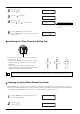
Press the [ ] key.
Press the [
] key.
3
Press the [ ] several times.
5
Press the [ENTER] key to enable the value.
Press the [MENU] key to go back to the screen shown
in the figure.
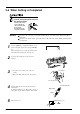
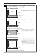
Evaluating the Offset Through a Cutting Test
The remaining cross-shaped area is used to check whether the
offset value is set correctly.
• When the offset value has been correctly set, the corners of
the figure should appear cleanly cut as shown in A of the
figure right.
• If the offset value is too small, the corners will appear
slightly rounded as illustrated by B; an offset value which is
too large will result in a cut figure similar to C.
When you are adjusting the blade offset, we recommend first adjusting the blade force and the amount of blade extension.
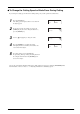
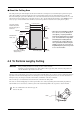
Changing the Speed When Raised (Up Speed)
With this machine, you can set the speed for movement to the next cutting location with the tool raised while cutting is in progress.
In cases such as when the material rises up over the platen and the surface of the material is damaged by the blade when the material
moves forward and backward while the tool is raised, you can avoid problems by lowering the speed.
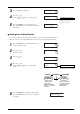
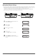
1
Press the [MENU] key several times until the screen
shown in the figure appears.
2
Press the [ ] key.
Press the [
] key.
4
Press the [ ] key.
Use the [
] and [ ] key to set the value.
FORCE 50gf
OFFSET 0.250mm
OFFSET 0.250mm
*0.275mm
20cm/s
50gf 0.275mm A
UNSETUP
FORCE 50gf
Setting range:
0 to 1.000 mm (in increments of
0.025 mm)
Blade-offset adjustment