USER'S MANUAL CM-500 CM-400 CM-300 Thank you very much for purchasing the CM-500/400/300. • To ensure correct and safe usage with a full understanding of this product's performance, please be sure to read through this manual completely and store it in a safe location. • Unauthorized copying or transferral, in whole or in part, of this manual is prohibited. • The contents of this operation manual and the specifications of this product are subject to change without notice.
For the USA NOTICE FEDERAL COMMUNICATIONS COMMISSION RADIO FREQUENCY INTERFERENCE STATEMENT This equipment has been tested and found to comply with the limits for a Class A digital device, pursuant to Part 15 of the FCC Rules. These limits are designed to provide reasonable protection against harmful interference when the equipment is operated in a commercial environment.
Table of Contents To Ensure Safe Use ....................................................................................................................... 2 About the Labels Affixed to the Unit ...................................................................... 5 1 Checking Supplied Items ...................................................................................................................... 7 2 Part Names and Functions .....................................................................
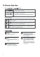
To Ensure Safe Use About and Notices Used for instructions intended to alert the user to the risk of death or severe injury should the unit be used improperly. Used for instructions intended to alert the user to the risk of injury or material damage should the unit be used improperly. * Material damage refers to damage or other adverse effects caused with respect to the home and all its furnishings, as well to domestic animals or pets.
Do not attempt to unplug the power cord with wet hands. Doing so may result in electrical shock. Do not use with a damaged power cord or plug, or with a loose electrical outlet. Use with any other power supply may lead to fire or electrocution. When unplugging the electrical power cord from a power outlet, grasp the plug, not the cord. When not in use for prolonged periods, unplug the power cord from the electrical outlet. Unplugging by pulling the cord may damage it, leading to fire or electrocution.
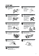
Use care to avoid pinching the fingers when placing the unit on the stand. 4 Use the joining screws to secure the unit to the stand. Doing so may result in injury. Failure to do so may result in falling of the unit, leading to injury. Roll material must be placed at a predetermined shaft position. Release the caster locks for the stand before attempting to move. Failure to do so may result in falling of the roll, leading to injury. Otherwise the unit may tip over and cause injury.
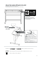
About the Labels Affixed to the Unit These labels are affixed to the body of this product. The following figure describes the location and content of these messages. Do not place hands near the platen while in operation. N'approchez pas vos mains du plateau de travail quand le chariot est en mouvement. Model name Rating label Use a rated power supply. ENGAGE セット RELEASE 解除 NOTICE ・Use the brake when you want to load a piece of material.
- MEMO - 6
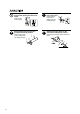
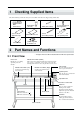
1 Checking Supplied Items Check the following to make sure that you received all the items that were shipped along with the unit. Blade Holder (XD-CH2) Power Cord: 1 Test-use Application Tape Material for Test Cuts Test use Water Based Fiber Tipped Pen Tweezers (for handling material) Replacement blade for separating knife CAMM-1 DRIVER for windows® 95 User’s Manual 2 Blade (ZEC-U5025) Part Names and Functions * The figure shows the CM-500 installed with the PNS-500 special stand.
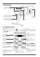
2-2 Rear View Sheet Loading Lever These raise and lower the pinch rollers. Power Connector [AC IN] This connector accepts standard AC power cord. Parallel (Centronics) Connector This is for connecting a computer with a parallel (printer) cable. Tray Use this to store blades or pens. Serial (RS-232C) Connector This is for connecting a computer with a serial (RS-232C) cable. Sheet Sensor 2-3 Operation Panel Blinking Cursor Used to select the desired item from the menu.
3 Setup 3-1 Setting Up and Connection Ground the unit with the ground wire. Failure to do so may result in risk of electrical shock in the even of a mechanical problem Install on a stable surface. Failure to do so may result in falling of the unit, leading to injury. Do not use with any electrical power supply that does not meet the ratings displayed on the unit. Use with any other power supply may lead to fire or electrocution. Use only with the power cord included with this product.
Connection Power outlet Power cord Power connector Parallel connector (Centronics) Serial connector (RS-232C) Parallel interface cable (Centyonics) Serial interface cable (RS-232C) *Parallel interface cable or Serial interface cable * Cables are available separately. One which you are sure matches the model of computer being used should be selected. 3-2 Turning on the Power Use the switch at the front-left surface of the unit to turn on the power. Press the side of the switch marked “ –”.
3-3 Selecting the Interface Make sure the settings for the computer (driver) match the settings for the CM-500/400/300 interface. The selected interface type and communication parameters are stored in memory even after the power is switched off. To change the interface type or the communication parameters, configurations must be re-entered. 1 2 3 Close the front cover and press the MENU key. The menu shown at right appears on the display.
4 Basic Operation 4-1 Installing a Blade Do not touch the tip of the blade with your fingers. Doing so may result in injury, and the cutting performance of the blade will be impaired. NOTICE 1 Be sure to support the tool mounting screw from below when installing the blade holder. Cutting quality may become poor if installed without supporting the screw in this way. Insert a blade into the blade holder until it snaps into place with an audible click.
How to Set the Cutting Speed (1) Close the front cover and press the MENU key until the message shown below appears. 1 CUT 0.250mm (2) Use the and Cutting Speed 50cm/s 30gf Setting range: 1—85 cm/s. (in increments of 1 cm/s.) keys to change the value, then press the ENTER key to accept the value. (3) To adjust speed during tool-up time or to adjust cutting quality, press the Use the and key until the screen shown below appears.
Material Loading Position :Grit Roller : Movable Pinch Roller (Middle) :Movable Pinch Roller (Left) : Movable Pinch Roller (Right) 6" (approx.152 mm 12" (approx.305 mm) Material 18" (approx.457 mm) 24" (approx.610 mm) 30" (approx.762 mm) 36" (approx.914 mm) 48" (approx.1219 mm) 54" (approx.1372 mm) The right-hand movable pinch roller can be moved within this range. When loading material with a width other than one indicated above, move the right-hand movable pinch roller.
To cut off a piece of material with the separating knife, load the media within the range shown below. Loading media outside this range may make it impossible to cut off the material with the separating knife. 13 mm (1/2") from the edge of the leftmost grit roller 37 mm (1-7/16") from the edge of the Rightmost grit roller Separable range Loading Roll Material * When performing lengthy cutting of 1.5 m (60") or more, please refer to the section " To Perform Lengthy Cutting" that follows this one.
4 Position so that the left-hand edge of the material lies over any one of the grit rollers. Move the material from side to side and position so that the right-hand edge of the material lies over the rightmost grit roller. With the material set in place, make sure the grit rollers are positioned correctly. Grit roller Sensor Grit roller 5 Load the material so that it lies over the sensor on the platen.
9 Close the front cover Close the front cover. Use the and keys to select [Roll], then press the ENTER key. * If cutting is to be performed from the front edge of the material, select "EDGE." 10 Press the key. The SETUP LED lights up, and the horizontal width of the material is detected and shown on the display. * If "EDGE" has been selected for the material, then after the width of the loaded material is detected, the front edge of the material is aligned with the cutting-start area.
To Perform Lengthy Cutting NOTICE When performing material feed or cutting, be sure to release the brake. Attempting to perform material feed or cutting with the brake engaged may make normal feed impossible and cause the material to slip. Have on hand a piece of material that's at least 50 mm (2") wider than the cutting width. The chance of the material slipping loose from the pinch rollers can be reduced by braking the shaft and loading the pulled-out material while it's in a tensioned state.
7 Use the control panel to make the following setting. SELECT SHEET ROLL EDGE PIECE Press or to select [ROLL]. Press . PRESS SETUP KEY Press WIDTH 14612 . LENGTH ------ Press . 1 CUT 0.250mm 50cm/s 30gf Press AREA REPLOT AREA MOVE Press Press . AXIS SUBMENU LENGTH < 1.0m> AREA MOVE or or to select the value. to change the value. LENGTH < 2.0m> Press or to select [AREA]. Press or to select [MOVE]. Press Press . Set this to the length of the material to be cut. .
4-3 About the Cutting Area The cutting area along the horizontal plane (the direction in which the tool carriage moves) is determined by the position of the pinch rollers. The workable area spans the length between the two rollers, minus a margin of about 1 mm (about 0.04") on both sides. If the material length is greater than 1,600 mm (62-15/16") when a flat material (paper) has been loaded, the CM-500/400/300 determines it to be a rolled material and sets the material length to 24,998 mm (984-1/8").
4-5 Cutting Test (How to Adjust Pen Force and Blade Extension) Before carrying out actual cutting, you may wish to perform a "cutting test" to check whether the unit produces the cutout satisfactorily. This is done by examining the results of the cutting test, and adjusting the blade force and the amount of blade extension. The cutting test should be repeated until the appropriate cutting conditions for the material in use are discovered.
If the results of steps 1 and 2 show that the cutting quality is not acceptable, refer to "Adjusting the Blade Force" to adjust the blade force. If adjusting the blade force doesn't improve the cutting quality, refer to "Adjusting the Blade Extension" to adjust the blade extension. After adjusting the blade extension, carry out a cutting test and adjust the blade force.
Incorrect cutting conditions may cause symptoms such as those described below. Blade force • The sheet is easily torn. • The cutter requires frequency replacement. • Cutting extends through the base paper, and normal advancing of the sheet becomes impossible. • The unit suffers damage. Blade offset Corners flare outward, with "horns." Too large Too large Too small Corners are rounded. Too small Some parts of the sheet remain uncut.
4-6 Downloading Cutting Data The unit will begin cutting when it receives cutting data sent from computer. Software Setting Make the settings described below to match the program that you're using. If you're outputting the data from a Windows-based program, select either [CM-500], [CM-400], or [CM-300] as the printer. If you're outputting the data from an MS-DOS-based program, selection the CM-500/400/300 as the output device.
4-7 Applying the Completed Cutout Once cutting has been completed, follow the procedure below for application instructions. • Make sure beforehand that the surface where the work is to be stuck is clean and free of all dust or oily deposits. • When applying the work to a transparent surface, such as a window, you can use a water-based pen (which can be wiped off afterwards) to mark guidelines on the reverse side of the glass, to aid in getting the work aligned properly.
4-8 When Cutting is Completed When not in use for extended periods, unplug the power cord from the electrical outlet. Failure to do so may result in danger of shock, electrocution, or fire due to deterioration of the electrical insulation. NOTICE 1 Do not leave the tool mounting screws tightened. Tightening the screw makes it more difficult to install the blade holder. Lower the sheet loading levers and remove the material. 2 (1) Loosen the tool securing screw on the cutting carriage.
5 Maintenance 5-1 Cleaning NOTICE Always turn off the CM-500/400/300 before cleaning it. Never lubricate the mechanisms. Do not clean with solvents (such as benzine or thinners). Cleaning the body Use a cloth moistened with water then wrung well, and wipe gently to clean. Wipe the operation panel and display gently with a clean, soft cloth. Cleaning the platen Use a cloth moistened with water then wrung well, and wipe gently to clean.
5-2 How to Replace the Separating Knife Make sure the power to the unit is off before attempting to replace the separating knife. Doing so may result in injury. If the separating knife, replace it with the replacement blade included with the CM-500/400/300. Follow the steps below to replace the blade. 1 Switch off the power to the CM-500/400/300. 2 Remove the separating knife. (1) Loosen the screw until it slips out. (2) Grasp the screw portion, and slowly pull it out in the direction of the arrow.
6 Using the Display Menus This section describes the basic steps for using the display menus. Use this information together with "7 Display Menus Flowchart" on the following page to make menu settings. Use the and keys to move the blinking cursor (" ") and choose a setting. Then use the and keys to change the value (or the selection) and enable the setting by pressing the ENTER key. 1 CUT 0.
7 Display Menus Flowchart For details about each of the menus, see the "8 Display Menu Lists." Power on MENU + Power on + Power on Openning message ENGLISH JAPANESE GERMAN FRENCH CM-500 Roland DG Corp. ENGLISH/JAPANESE/ GERMAN/FRENCH/ SPANISH/ITALIAN After loading a sheet, close the front cover. SELECT SHEET ROLL EDGE PIECE ROLL/EDGE/PIECE or Use to select. Press ENTER DEMO CUT or Use to select. Press ENTER to enable the setting.
AREA REPLOT AXIS SUBMENU CROP-MARK BASEPOINT->ENTER 0 0 ALIGNPOINT->ENTER 0 0 CROPMARK SETTING COMPLETED! CROPMARK SETTING FAILED,SET AGAIN SUBMENU CROPMARK UPDOWN OVER-CUT CALIB UPDOWN UP/DOWN ->ENTER MOVE ->CURSOR OVER CUT OVER CUT OFF Pressing ENTER moves the blade up or down. Pressing , , , or moves the cutter in the +Y, -Y, -X, or +X directions, respectively. STOP OFF/ON 1/2 CALIB X CALIB Y 0.00% 0.
8 Display Menu Lists This chart lists the menus of the CM-500/400/300 grouped by usage. Menus indicated by an Circle (" section at the end of the chart. Please refer to these additional explanations when using such menus. MENU ") are explained further in the Explanation Default Determining the type of sheet loaded SELECT SHEET This selects the type of material to be used ("ROLL," "EDGE," or "PIECE").
MENU Explanation Default AREA This moves the material by the length to be cut before actual cutting is performed, making it possible to ensure that the material will not slip or come loose during cutting. When performing continuous cutting on the same material, this can also be used to make sure that there is enough remaining material to cut the data that will be sent. 1.0 m AREA UNIT Sets the units used to specify length in display menu “AREA”. Units may be set to either “METRE” or “FEET”.
MENU Explanation Default TOOL-CNG COMMAND This is normally set to "IGNORE" when performing cutting. When a toolselection instruction (SP instruction) is sent from the computer while this is set to "EGNORE," the SP instruction is ignored and operation continues without pause. When set to "EFFECT," SP exchange instructions are accepted and operation pauses. If tool change is needed, open the front cover, change the tool, then press the ENTER key.
1 OVER CUT Cutting results differ as shown in the following figures depending on whether the Overcut function is on or off. OVER CUT: ON OVER CUT: OFF Cutting line Cutting line 2 ROTATE Whenever you employ the Rotate function (which allows you to rotate a character 90 degrees), the origin will be located at the material’s lower-right.
Do not place hands near the platen while in operation. Doing so may result in injury. • The crop mark setting cannot be made if the angle of the base point and the align point is more than 5 degrees. • Crop marks cannot be set when the "ROTATE" display menu is set to "90 deg." Load the material (with pre-printed graphics) and install the water based fiber tipped pen included with the CM-500/400/300. The alignment tool is installed in the same way as the blade holder.
9 About the Blades and Materials This section indicates the proper cutting conditions for various types of materials, as well as blade lifespans. Cutting conditions and blade life vary according to the hardness of the material and the usage environment. Making the settings for the conditions described below does not automatically guarantee attractive cutting results in all situations.
10 NOTICE Plotting on Paper Media Do not use coated paper. The coating may flake or peel off and adhere to the grit rollers, making it impossible to perform cutting (or plotting) correctly. Before cutting, plotting using pen and paper can ensure that your design is correct without wasting materials. This feature can also be used to plot template designs on thick materials that may not be able to be cut.
(1) Press the MENU key until the screen shown at right appears, then use the and keys to select "SUBMENU" and press the ENTER key. (2) Press the ENTER key, then press the MENU key twice the screen shown at right appears. Then use the and keys to select "TOOL-CHG" . (3) Press the ENTER key to display the screen shown at right, then use the select "EFFECT" and press the ENTER key. and keys to Depending on the setting made for "6.
Are the computer and the CM-500/400/300 connected correctly? Correctly connect the computer and the CM-500/400/300 (see “3-1 Setting Up and Connections” ). Is the interface setting correct? At the display menu, make the correct setting for the interface connecting the computer and the CM-500/400/300 (see “3-3 Selecting the Interface” ).
The material is not cut properly Are the blade and blade holder installed correctly and securely ? Install these so that there is no looseness (see “4-1 Installing a Blade” ). Is the blade chipped ? If it is, replace it with a new one (see “4-1 Installing a Blade” ). Check if there are any dirty deposits on the blade. If dirty, remove and clear the blade.
11-2 Error Messages An error message will appear if incoming data has any of the errors listed in table. Since the error is shown in the display for informational purposes, the data transfer continues and you are allowed to perform the next operation. To get the error message to go away, press the ENTER key. Note that even though the error message is no longer displayed after you press thee ENTER key, the CM-500/400/300 will retain in memory the fact that the error occurred.
12 Instruction Support Chart A "CAMM-GL III Programmer's Manual" is available for separate purchase for those wishing to create their own programs for this machine. For further information, please contact your authorized Roland dealer or service center.
13 Character Sets Automatic backspace 44
Specifications CM-500 Mechanism Media-movement method Driving method Digital control servo motor Maximum cutting area Acceptable media widths CM-300 CM-400 Width: 1195 mm (47") Width: 1000 mm (39") Width: 737 mm (29") Length: 24998 mm (984-1/2") Length: 24998 mm (984-1/2") Length: 24998 mm (984-1/2") Min. 90 mm (3-1/2") / Max. 1372 mm (54") Min. 90 mm (3-1/2") / Max. 1178 mm (46") Min. 50 mm (2") / Max.
( ) * The following conditions must be satisfied: - Material type: 3M Scotchcal Mastercut Film, ARLON Series 2100 - Special stand (a roll material must be set at the rear and on the inner sheet hanger) - Side margins: 25 mm (1") or more for both the left and right margins - Front margin: 25 mm (1") or more (After loading the material, using the display menu to select “EDGE” as the material type automatically sets a front margin of 25 mm (1").
Interface specifications Parallel Standard In compliance with the specifications of Centronics Input signals STROBE (1 BIT), DATA (8 BITS) Output signals BUSY (1 BIT), ACK (1 BIT) Level of input/output signals TTL level Transmission method Asynchronous Serial Standard RS-232C specifications Transmission method Asynchronous, duplex data transmission Transmission speed 2400, 4800, 9600, 19200 (Selected using panel keys.) Parity check Odd, Even, or None (Selected using panel keys.
Please read this agreement carefully before opening the sealed package or the sealed disk package Opening the sealed package or sealed disk package implies your acceptance of the terms and conditions of this agreement. If you do NOT accept this agreement, retain the package UNOPENED. (This product is just one of included items. Please be aware that any amount of the purchase price will not be refunded for return of this product as a single item, regardless of whether the package is opened or unopened.