Owner’s Manual Congratulations on your purchase of the Roland DIF-AT24. Before using this unit, carefully read the sections entitled: “USING THE UNIT SAFELY” (p. 2, 3) and “IMPORTANT NOTES” (p. 4). These sections provide important information concerning the proper operation of the unit. Additionally, in order to feel assured that you have gained a good grasp of every feature provided by your new unit, Owner’s Manual should be read in its entirety.
USING THE UNIT SAFELY The symbol alerts the user to important instructions or warnings.The specific meaning of the symbol is determined by the design contained within the triangle. In the case of the symbol at left, it is used for general cautions, warnings, or alerts to danger. Used for instructions intended to alert the user to the risk of death or severe injury should the unit be used improperly.
104 • Try to prevent cords and cables from becoming entangled. Also, all cords and cables should be placed so they are out of the reach of children. ................................................................................................ 106 • Never climb on top of, nor place heavy objects on the unit. ................................................................................................ 108c • Disconnect all cords coming from external devices before moving the unit. ...................
IMPORTANT NOTES In addition to the items listed under “USING THE UNIT SAFELY” on page 2, please read and observe the following: 291a Power Supply 307 • Before connecting this unit to other devices, turn off the power to all units. This will help prevent malfunctions and/or damage to speakers or other devices. Placement 352a • This device may interfere with radio and television reception. Do not use this device in the vicinity of such receivers.
Contents Main Features ....................................................................................................................... 1 USING THE UNIT SAFELY ............................................................................................... 2 IMPORTANT NOTES ......................................................................................................... 4 Panel descriptions ................................................................... 6 Front Panel .....................
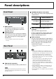
Panel descriptions Front Panel MASTER CLK (Master clock) switch This switches the master clock (sampling clock) synchronization. MASTER CLK switch Set to [R-BUS] When using the R-BUS device connected to the R-BUS connector as the master clock. Set to [ADAT] When using the digital device connected to the ADAT OUT/IN connector as the master clock ADAT indicator This indicator will light green if an ADAT interface signal is being input to the ADAT digital IN connector.
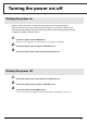
Turning the power on/off Turning the power on Before you turn each device on, make sure that all devices are connected correctly. Once the connections have been completed, turn on power to your various devices in the order specified. By turning on devices in the wrong order, you risk causing malfunction and/ or damage to speakers and other devices. 1 Turn on the power of your R-BUS device. When power is supplied to the DIF-AT24, its power indicator will light.
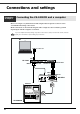
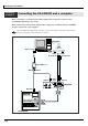
Connections and settings Connection example 1 Connecting the VS-2400CD and a computer Here's an example of synchronization with computer-based sequencer software or the VS-2400CD functioning as the master. Make connections as shown in the diagram. This example uses the UA-1000 to perform input/output with the computer via USB 2.0. To prevent malfunction and/or damage to speakers or other devices, always turn down the volume, and turn off the power on all devices before making any connections. PC USB 2.
Connections and settings Settings ■ Sampling Frequency settings Set the sampling frequency of your sequencer software, the VS-2400CD, and the UA-1000 to the same setting (44.1 kHz or 48 kHz). ■ Master Clock settings Master clock device VS-2400CD Sequencer software VS-2400CD setting DIF-AT24 MASTER CLK switch PROJECT PARAMETER screen ❍ MASTER CLOCL ................INT PROJECT PARAMETER screen ❍ MASTER CLOCL ................
Connections and settings Connection example 2 Connecting the VS-2400CD and a computer Here's an example of synchronization with computer-based sequencer software or the VS-2400CD functioning as the master. Make connections as shown in the diagram. This example uses an ADAT interface and MIDI interface connected to your computer. To prevent malfunction and/or damage to speakers or other devices, always turn down the volume, and turn off the power on all devices before making any connections.
Connections and settings Settings ■ Sampling Frequency settings Set the sampling frequency of your sequencer software and the VS-2400CD to the same setting (44.1 kHz or 48 kHz). ■ Master Clock settings Master clock device VS-2400CD Sequencer software VS-2400CD setting DIF-AT24 MASTER CLK switch PROJECT PARAMETER screen ❍ MASTER CLOCL ................INT PROJECT PARAMETER screen ❍ MASTER CLOCL ................R-BUS R-BUS ADAT You'll also need to set the Master Clock for your sequencer software.
Connections and settings Connection example 3 Connecting the VS-2400CD and an ADAT device This example allows digital audio signals to be transferred. Make connections as shown in the diagram. To prevent malfunction and/or damage to speakers or other devices, always turn down the volume, and turn off the power on all devices before making any connections.
Connections and settings Connection example 4 Connecting the VS-2400CD with an ADAT device and BRC The BRC is used to operate the VS-2400CD and ADAT device in synchronization. Make connections as shown in the diagram. To prevent malfunction and/or damage to speakers or other devices, always turn down the volume, and turn off the power on all devices before making any connections.
Connections and settings Settings ■ Sampling Frequency settings Set the sampling frequency of the VS-2400CD and ADAT device to the same setting (48 kHz). ■ Master Clock settings Master clock device VS-2400CD ADAT device VS-2400CD setting PROJECT PARAMETER screen ❍ MASTER CLOCL ................INT PROJECT PARAMETER screen ❍ MASTER CLOCL ................R-BUS DIF-AT24 MASTER CLK switch R-BUS ADAT You'll also need to set the Master Clock for the ADAT device.
Connections and settings Connection example 5 Using the DIF-AT24 as an additional MIDI OUT for the MV-8000 Make connections as shown in the diagram. To prevent malfunction and/or damage to speakers or other devices, always turn down the volume, and turn off the power on all devices before making any connections. In order to make these connections, the MV8-OP1 (audio I/O expansion; sold separately) must be installed in the MV-8000.
Information When you need repair service, call your nearest Roland Service Center or authorized Roland distributor in your country as shown below. AFRICA EGYPT Al Fanny Trading Office 9, EBN Hagar A1 Askalany Street, ARD E1 Golf, Heliopolis, Cairo 11341, EGYPT TEL: 20-2-417-1828 REUNION Maison FO - YAM Marcel 25 Rue Jules Hermann, Chaudron - BP79 97 491 Ste Clotilde Cedex, REUNION ISLAND TEL: (0262) 218-429 SOUTH AFRICA That Other Music Shop (PTY) Ltd. 11 Melle St.
VM-7100/7200 と接続する場合 VM-7100/7200 のシステム・バージョンが 1.7 未満の場合、DIF-AT24 は正常に動作しません。 以下の方法で VM-7100/7200 のバージョンを確認し、必ず 1.7 以降にバージョンアップして ください。 バージョンアップに関しては、最寄の弊社営業所またはローランド・サービス・ステーション までお問い合わせください。 ■ バージョンの表示方法 1 2 3 VM-7100/7200 を VM-C7100/C7200 と接続します。 電源を入れ、起動させます。 [On Display]を押しながらテン・キー[0]を押します。 バージョン表示画面になり、次のように表示されます。 「Unit X Version : 1.XXX」 4 画面の「1.