
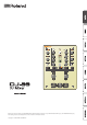
Operation Manual


7
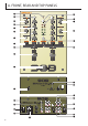
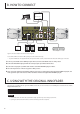
A. FRONT, REAR AND TOP PANELS
1
POWER indicator
LED will be lit when the unit is POWER ON
2
Input selector
Assign the input source of CH1 & CH2.
3
MIC level knob
Adjust the microphone input level.
4
TRIM level knob
Adjust the input level for CH1 & CH2.
5
Channel EQ knob
Adjust the EQ (HI/MID/LOW) for CH1 & CH2.
6
PHONES level knob
Adjust the headphones output level.
7
Channel Fader curve adjustment knob
Adjust the shape of the channel fader curve from a fast cut or to a slow fade.
8
Channel Fader reverse switch
Press to reverse the direction of the channel fader.
9
CUE button
Select the channel(s) to be monitored.
10
Channel Fader
Adjust the volume for CH1 & CH2.
11
Crossfader
Mix the sound from CH1 & CH2.
12
PFL/MASTER selector
Determine the level meter mode.
PFL
left side of the meter will indicate monaural level of CH1, and right side
of the meter will indicate monaural level of CH2.
MASTER show the master output level
13
PFL/MASTER level meter
Show the level depending on the position of PFL/MASTER selector
14
MASTER level knob
Adjust the master output level.
15
BOOTH level knob
Adjust the booth output level.
16
Crossfader curve adjustment knob
Adjust the shape of the crossfader curve from a fast cut for scratching or to a slow fade
for mixing.
17
Crossfader reverse switch
Press to reverse the direction of the crossfader.
18
MIC input jack (1/4”)
Connect to your microphone.
19
Headphones Monitoring selector
Select the source to be monitored with headphones.
CUE CH1 & CH2
MIX CH1 & CH2 at left side, and Master output at right side
MASTER Master output
20
PHONES output jack (1/4” + 3.5 mm)
Connect to your headphones.
21
BOOTH output jack (RCA)
Connect to your active monitors.
22
MASTER output jack (1/4” stereo)
Connect to your active speakers.
23
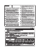
POWER switch
Turn this unit power ON/OFF.
* Once everything is properly connected, be sure to follow the procedure below to
turn on their power. If you turn on equipment in the wrong order, you risk causing
malfunction or equipment failure.
When powering up:
this unit
0
connected devices
When powering down:
connected devices
0
this unit
* Before turning the unit on/o, always be sure to turn the volume down. Even with
the volume turned down, you might hear some sound when switching the unit on/
o. However, this is normal and does not indicate a malfunction.
* If you need to turn o the power completely, rst turn o the unit, then unplug the
power cord from the power outlet. Refer to “To completely turn o power to the
unit, pull out the plug from the outlet” (p. 2).
24
AC IN Connector
Connect to the main AC power with the power cord. (package included)
25
Fuse holder
If the power does not turn on even though the unit is correctly connected, it could be
that the fuse has blown. Check the fuse and replace it.
Caution when replacing the fuse
* Failure to observe the following cautions may result in electric shock.
5 Never connect the unit to an electrical power source while
replacing the fuse.
5 When replacing the fuse, use only the specied type
(T315mAL250V) and size (5 ф x 20 mm).
5 If you cannot obtain a replacement fuse or if the unit still does not
work even after you replace the fuse, contact the Roland Service
center.
26
DVS SEND jack (RCA)
Connect to the inputs of your DVS audio interface.
27
DVS RETURN jack (RCA)
Connect to the outputs of your DVS audio interface.
28
GND terminal
Connect to the ground leads of your turntable.
29
LN/PH selector
When connecting the turntable with moving magnet cartridge, be sure the switch is
in “PH” position. When using the line level device, select “LN.” Always be sure the main
power is OFF before switching.
30
LN/PH input jack (RCA)
Connect to your turntable or line level device.
31
CD input jack (RCA)
Connect to your CD player.