
User Manual


10
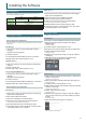
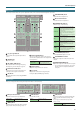
Panel Descriptions
1
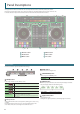
DC IN jack
Connect the included AC adaptor here.
* Place the AC adaptor so the side with the indicator (see illustration)
faces upwards and the side with textual information faces downwards.
The indicator will light when you plug the AC adaptor into an AC outlet.
Power cord
AC Outlet
Indicator
* To prevent the inadvertent disruption of power to your unit (should the
plug be pulled out accidentally), and to avoid applying undue stress to
the jack, anchor the power cord using the cord hook, as shown in the
illustration.
2
[POWER] switch
This turns the power on/o.
* The power to this unit will be turned o automatically after a
predetermined amount of time has passed since it was last used for
playing music, or its buttons or controls were operated (Auto O
function).
If you do not want the power to be turned o automatically, disengage
the Auto O function.
For details on how to disable this function, refer to p. 22.
NOTE
5 Any settings that you are in the process of editing will be lost when
the power is turned o. If you have any settings that you want to
keep, you should save them beforehand.
5 To restore power, turn the power on again.
3
[MIC SENS] knob
Adjusts the mic input sensitivity.
4
MIC IN jack
Connect your microphone here.
You can use any one of three types of plugs (XLR, TRS, phone).
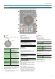
* Pin assignment of MIC IN jack
1: GND
2: HOT
3: COLD
GND (SLEEVE)
HOT
(TIP)
COLD (RING)
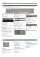
5
MASTER OUT 1 (L / R) connectors, 2 (L / R) jacks
Connect your powered speakers or power amp here.
* Pin assignment of MASTER OUT 1 connectors
6
BOOTH OUT (L / R) jacks
These are the output jacks for booth monitoring.
* Pin assignment of BOOTH OUT jacks
7
INPUT (CH 1–CH 4) jacks
These jacks input sound to channels 1–4. The CH1 and CH2 INPUT jacks
support phono input from MM-type cartridges.
Set the [INPUT SELECT] switch appropriately for the device you’re
connecting.
8
PHONO GROUND terminal
If a turntable (analog) is connected to the CH1 or CH2 INPUT jacks, connect
the turntable’s ground terminal here. This suppresses noise from the
turntable.
* Depending on the circumstances of a particular setup, you may
experience a discomforting sensation, or perceive that the surface feels
gritty to the touch when you touch this device, or the metal portions of
other objects. This is due to an innitesimal electrical charge, which is
absolutely harmless. However, if you are concerned about this, connect
the PHONO GROUND terminal with an external ground. When the unit
is grounded, a slight hum may occur, depending on the particulars of
your installation. If you are unsure of the connection method, contact
the nearest Roland Service Center, or an authorized Roland distributor,
as listed on the “Information” page.
Unsuitable places for connection
5 Water pipes (may result in shock or electrocution)
5 Gas pipes (may result in re or explosion)
5 Telephone-line ground or lightning rod (may be dangerous in the
event of lightning)
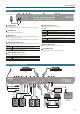
9
MIDI OUT connector
This outputs MIDI messages such as MIDI clock.
10
USB HOST ports
These are USB audio input ports.
Both ports 3 and 4 can supply USB bus power.
* For more about devices that can be connected, refer to the Roland
website.
11
PC port
Use the included USB cable to connect this port to your computer.
To connect this to your computer, you must install the USB driver.
& “Installing the Software” (p. 3)
Computer
* Use the cord hook to secure the USB cable as shown in the illustration.
This prevents the plug from being pulled out, or strain from being
applied to the port.
To prevent malfunction and equipment failure, always turn down the volume, and turn o all the units before making any connections.
Rear Panel (Connecting Your Equipment)