Manual P5/EP5 PMV Valve Control System alve Control System –1–
Manufacturers declaration • Hersteller-Erklärung • Déclaration de fabricant GB Manufacturers declaration in compliance with EC directive 89/392/EEC, annex II B and 89/336/EEC.
Contents Page 1. Introduction 1.a Storage Instructions, Storage Seal 4 5-6 2. Function 7 3. Air requirements 8 4. Installation 8 5. Connections 9 6. Front cover and the indicator cover 10 7. Span and zero adjustment 11 8. Indicator adjustment 12 9. Cam adjustment 12 10. Dampers 12 11. I/P Unit, EP5 13 12. How to mount the I/P Unit 14 13.
1. Introduction Always check www.pmv.nu for latest edition of manual. The P5 Valve Control System is a valve positioning system from PMV with a modular design concept. The base unit of the system is the pneumatic positioner, used in either single or double acting applications. P5 comes standard with built in dampers, a 5 mm high gain spool valve assembly, gauge ports and an O-ring sealed housing. The housing utilizes a unique O-ring seal that can be adjusted to a sealed or drained position.
1.a Storage instructions PMV Positioner and feedback module storage and handling procedures PMV Positioners and feedback modules are precision instruments which should be stored and handled accordingly to avoid problems or damage. Electropneumatic positioners/feedback modules contain electronic components which can be damaged by exposure to excessive water. Appropriate precautions should be taken to protect units while in storage.
Storage Seal P5/EP5 is supplied with all enclosure entry points sealed.The seal is only a storage seal, not to be used as seal when P5/EP5 is in operation. If Storage Seal is removed or damaged, make sure all open enclosure entry points are proper resealed before further shipping or storage. Use circular stickers marked I, S and OUT, supplied on Storage Seal or vapour proof tape.
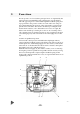
2. Function The P5 operates on a force balance principal. Force is originated by the signal pressure transmitted through a diaphragm on to the balance arm. The opposing force is achieved through the feedback spring and is proportional to the position of the lower arm. The lower arm position is determined by the position of the cam which is secured to the spindle and connected to the actuator shaft thus providing the feedback from the actuator/valve.
3. Air requirements Maximum supply pressure is 1 MPa (150 psi). Supply air shall be clean, dry and free from oil, water, moisture, foreign parts and debris. The air shall be freeze-dried or similar to a dew point of at least 10°C (18°F) below lowest expected ambient temperature. A <40µ filter/regulator is recommended to be installed as close to P5/EP5 as possible to ensure proper supply air quality.
5. Connections Air connections are tapped for 1/4" G or NPT male connectors and are clearly marked. Gauge ports are for 1/8" G or NPT. We recommend use of tape, Loctite® 577 or similar user preferred for sealing. Electrical connection on I/P unit accepts 1/2" NPT or PG 13,5 (M20) cable gland. Port I Port S Port C1, C2 OUT Port Ip Port IE Port P Input instrument pneumatic signal 20-100kPa (3-15 psi) Supply air, maximum 1 MPa (150 psi) Minimum 0,15 MPa (21 psi) for EP5 Actuator connections (0,2-1 MPa).
6. Front cover and indicator cover The front cover of P5 is secured to the pneumatic unit with four captured screws and sealed with an O-ring 1. The O-ring can be looped over notches 2 in the front cover to allow for drainage. There are eight locations on the front cover where the O-ring can be looped. This O-ring system is common to the Pneumatic unit , I/P unit and Feedback unit in the PMV Valve Control System P5.
7. Calibration P5/EP5 is when shipped from PMV precalibrated for 90 ±0,5 deg rotation, (can also be 30, 45 or 60 deg, see installed cam). For most applications the valve closed position is more critical than valve open position, most attention should be paid at valve closed position. Always start calibration procedure by applying 0 % input signal, then adjusting zero. P5/EP5 is calibrated by turning thumb wheels 1 & 4. Arrows on arm 5 indicate turning direction of thumb wheels.
8. Indicator adjustment To adjust the indicator, take off front cover and pull the indicator upwards until it comes off the Allen screw. Before installing the indicator make sure that the Allen screw is tightened. Press the indicator on the screw and adjust it by rotating clockwise to desired position. 9. Cam adjustment With the cover and indicator removed, loosen the screw 1 and turn the cam locking nut 2 counterclockwise until the cam loosens.
11. I/P Unit, EP5 WARNING! Units installed in hazardous areas must have proper approvals. The I/P unit is mounted directly on top of the positioner unit. No external air supply is needed since the I/P unit is supplied with air from the positioner unit. Port I on the positioner unit will be plugged when the I/P unit and the appropriate gauge block gasket installed.The I/P unit accepts a 4-20 mA input signal. The I/P unit is equipped with a built in 30 micron filter (Fig 4).
12. How to mount the I/P Unit to the positioner Unit Switch off supply air and disconnect input signal – port I. Loosen screws 3 and remove connection block 1, the gauge or plug from port Ip, the fitting from port I and existing gasket 4. Carefully install gasket 6 supplied together with I/P unit. When correct installed port I will be blocked by the gasket. Make sure that relief valve spring 5 is installed properly. Install the connection block 1 to the positioner unit 2. Remove cover on I/P unit.
13. Maintenance Pilot valve To remove the pilot valve for cleaning or inspection, remove the screw 1 and carefully lift out the complete assembly 2. Gently remove the spool 3 from the block and clean the parts, using methylate cleaner or similar. Blow the parts dry with compressed air. Install the spool into the pilot valve housing, place it on a flat surface, then lift it carefully in one end. Before reaching 20 deg angle the spool should move by itself.
Diaphragm If P5 is equipped with I/P unit (EP5), the I/P unit must be removed to access the diaphragm. When installing the diaphragm make sure to place one washer on each side of the diaphragm. Put some Loctite 577 on the thread, install the screw 3 and tighten. Make sure the diaphragm is centered. Check the O-ring for the diaphragm cover 2, install the O-ring into the positioner housing, then install cover 2. Secure crosswise with screws 1, first turn loosely. Torque shall be 4,5 Nm (40 in-lbs).
Feedback spring 2 Once the front cover and indicator are removed, the feedback spring can be easily accessed. Hold the spring 1 from the top, pull down and out. When installing, hold the assembly at the top, guide the lower part to position on the zero screw, then press down until it fits easily under the balance arm 2. Make sure that the assembly is aligned properly against the lower arm and the notch is engaged in the tab on the balance arm 2.
Lower arm Once the front cover is removed, the lower arm can be easily accessed. Remove the indicator, feedback spring and the cam. Loosen screw 2 and remove twist stop 1. Remove screw 3, lower arm 4, rod 5 and spring 6. Check rod and lower arm for wear, replace if necessary. Clean the rod and install it in the lower arm. The lower arm should move easily and smoothly.
Filter plug Caution! Do not operate the unit without filter and filter plug installed. Do not attempt to unscrew filter plug while positioner is pressurized. EP5 is equipped with a built in secondary filter located on the side of the I/P unit. For replacement or inspection, make sure that positioner unit is not pressurized, then unscrew filter plug 1. Remove filter 3 and install a new into the filter plug . Check condition of O-ring 2 and filter compartment.
14. Feedback Unit See feedback module instructions for connections and calibration. The P5 or EP5, Valve Control System, can easily be equipped with a Feedback unit, model F5. This unit will mount directly on top of the Pneumatic positioner replacing the positioner front cover. The O-ring located on the bottom of the Feedback unit, F5, will provide the same sealing or draining capabilities as the front cover.
15. Trouble shooting Note: All PMV-positioners are serialized. Please note down, and provide the serial number when contacting the factory for trouble shooting or service. Signal change results in actuator running to end positions. — Check coupling between positioner and actuator. — Check cam position and locking screw. — Check input signal. Signal change has no effect on the actuator position. — Check indicator and screw. — Check air supply to positioner and tubing to the actuator.
17.
18.
Approvals E5-IS/EU – 24 –
Approvals E5-EX/EU – 25 –
Approvals E5-IS/US & E5-EX/US 1 – 26 –
Approvals E5-IS/US & E5-EX/US 2 – 27 –
WARNING! Installation of any hazardous area equipment should be made in accordance with hazardous area installation codes and also of course to the installation to the installation and operating instructions provided. The manufacturer cannot be held responsible for incorrect installation or any customer modifications to, or repair of, a certified instrument as this may invalidate the certified design. If a certified instrument shoult fail, no attempt should be made by the user to effect repair.
FM – 29 –
CSA – 30 –
CENELEC ATEX – 31 –
Palmstiernas Instrument AB Korta Gatan 9 SE-171 54 Solna SWEDEN Tel: +46 (0) 8 555 106 00 Fax: +46 (0) 8 555 106 01 E-mail: info@pmv.nu Internet: www.pmv.nu SUBSIDIARIES: PMV GmbH Sperweg 16 D-41468 Neuss GERMANY Tel: +49 (0) 2131 795 74-80 Fax: +49 (0) 2131 795 74-99 E-mail: info@pmv-germany.de Internet: www.pmv-germany.de PMV-USA, Inc 1440 Lake Front Circle Unit 160 The Woodlands, Texas 77380 USA Tel: +1 281 292 7500 Fax: +1 281 292 7760 E-mail: pmvusa@pmvusa.com Internet: www.pmvusa.