USER’S MANUAL To ensure safe usage and full performance of this product, please be sure to read through this manual completely. To ensure immediate access whenever needed, store this manual in a safe location. Unauthorized copying, quotation, or translation of this manual, in whole or in part, without the written approval of Roland DG Corp., is prohibited. The contents of this document and the specifications of this product are subject to change without notice. Roland DG Corp.
For the USA FEDERAL COMMUNICATIONS COMMISSION RADIO FREQUENCY INTERFERENCE STATEMENT This equipment has been tested and found to comply with the limits for a Class A digital device, pursuant to Part 15 of the FCC Rules. These limits are designed to provide reasonable protection against harmful interference when the equipment is operated in a commercial environment.
Contents To Ensure Safe Use......................................................................................4 Important Notes on Handling and Use...............................................................9 About Operation Manuals..................................................................................10 Documentation Included with the Machine.........................................................................10 How to Display Help for Software..........................................
Contents 3-4 Starting and Stopping Printing...............................................................52 Starting Printing...............................................................................................................................52 Stopping Printing Operations.....................................................................................................54 Chapter 4 More Advanced Operations..............................................................
Contents 5-5 The Replacement of the Head Cap.......................................................98 The Replacement Cycle for the Head Cap..............................................................................98 5-6 Head Replacement................................................................................99 The Replacement Cycle for the Head.......................................................................................99 How to Replace the Head......................................
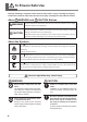
To Ensure Safe Use Improper handling or operation of this machine may result in injury or damage to property. Points which must be observed to prevent such injury or damage are described as follows. About WARNING and WARNING CAUTION Notices Used for instructions intended to alert the user to the risk of death or severe injury should the unit be used improperly. Used for instructions intended to alert the user to the risk of injury or material CAUTION damage should the unit be used improperly.
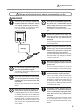
To Ensure Safe Use Danger of electrical short, shock, electrocution, or fire WARNING Connect to an electrical outlet that complies with this machine’s ratings (for voltage, frequency, and current). Incorrect voltage or insufficient current may cause fire or electrical shock. Never place any flammable object nearby. Never use a combustible aerosol spray nearby. Never use in any location where gases can accumulate. Combustion or explosion may be a danger.
To Ensure Safe Use Important notes about the power cord, plug, and electrical outlet Never place any object on top or subject to damage. Never bend or twist with undue force. Never pull with undue force. Never bundle, bind, or roll up. 6 Never allow to get wet. Never make hot. Dust may cause fire.
To Ensure Safe Use The head area becomes hot WARNING Never touch the head immediately after printing has finished. Doing so may cause burns.
To Ensure Safe Use Warning Label Warning label is affixed to make areas of danger immediately clear. The meaning of the label is as follows. Be sure to heed its warnings. Also, never remove the label or allow it to become obscured. Caution: High Temperature Never touch immediately after printing.
Important Notes on Handling and Use This machine is a precision device. To ensure the full performance of this machine, be sure to observe the following important points. Failure to observe these may not only result in loss of performance, but may also cause malfunction or breakdown. This Machine is a Precision Device. Handle carefully, and never subject the machine to impact or excessive force. Never print material outside the range of specifications.
About Operation Manuals Documentation Included with the Machine The following documentation is included with the machine. MPX-90 User’s Manual (this manual) This describes important notes for ensuring safe use, and explains how to install and operate the machine. It also explains how to install and operate included software. Be sure to read it first. METAZA Driver Online Help Roland METAZAStudio Online Help Roland SFEdit2 Online Help Dr.
About Operation Manual How to Display Help for METAZA Driver You can display Help for METAZA driver by conducting the following operation after installing METAZA driver. P.25, “Installing METAZA Driver” Procedure Windows 7 From [Start] menu, click [Control Panel] → [Hardware and Sound] → [Devices and Printers]. Windows Vista From [Start] menu, click [Control Panel] → [Hardware and Sound] → [Printers].
About Operation Manual 12 Click [Help]. METAZA Driver help appears.
Chapter 1 Getting Started 1-1 About the Machine..................................................................14 Features.....................................................................................14 1-2 Names and Functions.............................................................15 This Machine..............................................................................15 1-3 Checking the Included Items..................................................
1-1 About the Machine Features This machine is a metal printer. It prints images by striking detailed points using a marking pin mounted in a head.
1-2 Names and Functions This Machine Main Unit Cover Close the cover when making print. Hold the middle area of the cover as shown in the figure below when opening it. Knob Determine the head position based on the surface height of the material when performing printing without using a head cap. Head unit Move the head unit and align the end handle (marking pin) of the head to the surface of material. Head Power/Movement button Pressing this makes the light come on and switches on the power.
1-2 Names and Functions Head (MPH-90) Printing is performed on material using with a marking pin. Diamond is attached to the tip of the marking pin. Since the head is a consumable part, replace it at an appropriate timing. P. 99, “The Replacement Cycle for the Head” Marking pin Material Retainers Adhesive sheet This is used to fix material on a table. Material is placed on the adhesive sheet, which then holds the material in place.
1-3 Checking the Included Items The following items are packed together with the unit. Make sure they are all present and accounted for.
18
Chapter 2 Installation and Setup 2-1 Installation...............................................................................20 Installation Environment ............................................................20 Removing and storing the retainers...........................................21 2-2 Cable Connections.................................................................23 Connecting the machine to a power supply...............................23 2-3 Installing the Software.....................
2-1 Installation Installation Environment Install in a quiet, stable location offering good operating conditions. An unsuitable location can cause accident, fire, faulty operation, or breakdown. CAUTION Install in a location that is level and stable. Installation in an unsuitable location may cause an accident, including a fall or tip over. Never install in a location subject to wide fluctuations in temperature or humidity. Never install in a location subject to shaking or vibration.
2-1 Installation Removing and storing the retainers Retaining materials are attached to protect the machine from vibration during shipment. Remove these after emplacement. Remove all Retaining materials. Any that remain may cause faulty operation or breakdown when the power is switched on. The retaining materials and package are required when moving the machine to a different location. Store them carefully so that they do not get misplaced.
2-1 Installation Storing the retainers Keep the retaining materials by mounting them to the position shown in the figure.
2-2 Cable Connections Connecting the machine to a power supply At this time, the connection to the computer must not be made yet. Failure to follow the correct procedure may make installation impossible. You make the connection to the computer when you install METAZA driver. P. 25, “Installing METAZA Driver” WARNING Do not use with any electrical power supply that does not meet the ratings displayed on the AC adapter. Use with any other power supply may lead to fire or electrocution.
2-3 Installing the Software System Requirements Windows XP Home Edition (32/64-bit edition) Windows XP Professional (32/64-bit edition) Windows Vista Home (32-bit edition) Windows Vista Business (32/64-bit edition) Windows 7 Professional (32/64-bit edition) (*2) Operating system (*1) The minimum required CPU for the operating system (At least Pentium 4 3.
2-3 Installing the Software Installing METAZA Driver Make sure to connect the machine to a computer by following the given procedure. Failure to follow the correct procedure may make installation impossible. Procedure Before you start installation and setup, make sure the USB cable is NOT connected. Log on to Windows as “Administrators.” Insert the Roland Software Package CD-ROM into the computer. When the automatic playback window appears, click [Run menu.exe].
2-3 Installing the Software Click of the install menu window and setup guide window. Installing the Software Procedure Display the window for the install menu of the software. Follow the messages to install the software. Click [Install] of the program you want to install. The [User Account Control] appears, click [Allow], and install the softwares. 26 When all installation finishes, click of the install menu. Remove the CD-ROM from the CD-ROM drive.
2-4 METAZAStudio Settings Making the Setting for the Printer After you finish installing and setting up METAZAStudio, continue by making the setting for the printer. Be sure to make the setting before use. Procedure From [Start] menu, click [All Programs] (or [Programs]) → [Roland METAZAStudio] → [METAZAStudio]. METAZAStudio starts. Click [File] → [Set up the printer]. The [Print Setup] dialog box appears. Click the arrow shown in the figure, then select [Roland MPX90]. Click [OK].
28
Chapter 3 Making Prints 3-1 Switching the Power On and Off ...........................................30 Switching On the Power ............................................................30 Switching Off the Power.............................................................31 3-2 Getting Ready.........................................................................32 The Printable Area......................................................................32 Head Caps .......................................
3-1 Switching the Power On and Off Switching On the Power Procedure Make sure that the stopper contacts the ring and the knob is tightened as shown in the figure . In the case as shown in the figure , and then tighten the knob. , loosen the knob to make it into the state shown in the figure OK Ring OK Knob The center of the knob must be positioned above this marking. Stopper Not OK Ring Tighten Loosen Press the Power/Movement button.
3-1 Switching the Power On and Off Description When the power is ON in the state shown in the figure , there are cases where the power lamp blinks and an error occurs immediately after the initial operation is completed. To clear the error, take the procedure and press the Power/Movement button. The power lamp stops blinking and lights. Switching Off the Power Hold down the Power/Movement button for one second or longer. The light goes dark and the power is switched off.
3-2 Getting Ready The Printable Area The machine's printable area is as follows. Top view of the table Center line Printable Area 50mm × 50mm Center line Maximum Printable Area (80mm × 80mm) The setting by METAZA Driver is required. If an image exceeds the printable area, the print result might become uneven in the outside of the printable area. Head Caps Using the head cap is usually recommended.
3-2 Getting Ready Preparing Material to Print Prepare material that meets all of the following conditions. Thickness *1 0.3 to 40 mm (0.012 to 1.5 in.) Size *1 When using the adhesive sheet: 100mm (3.9 in.) (W) × 200mm (7.9 in.) (L) or less, or 200mm (7.9 in.) (W)× 100mm (3.9 in.) (L) or less. When using the center vise: 60 mm (2.3 in.) (W) × Length of 200mm (7.9 in.) (L) or less, or 200mm (7.9 in.) (W) × 60 mm (2.3 in.) (L) or less.
3-2 Getting Ready Cross-section of printing material When using an adhesive sheet or a center vice. There must be no unevenness on the print surface. *4 Not OK Not OK Edge of the material is too high. L-shape *4 Materials that cannot be used are those of which unevenness comes into contact with the moving part of the machine when material is set or when printing is made. When using an adhesive sheet. The back surface must be flat, with no difference in level.
3-2 Getting Ready Conditions for Material When Printing Curved Surfaces *5 The table and figure below show the printing-assured area and the area reached by the marking pin with respect to the diameter of the cylinder. Note, however, that the following conditions are assumed. The head cap is used. The material has circularity. Diameter of cylindrical material 10 mm (0.3 in.) 20 mm (0.7 in.) 30 mm (1.1 in.) Recommended printable area (A) 2.0 mm (0.079 in.) 2.8 mm (0.11 in.) 3.4 mm (0.14 in.
3-2 Getting Ready Loading Material Using the Adhesive Sheet Procedure Switch on the power P.30, "Switching On the Power" Make sure that the stopper contacts the ring and the knob is tightened as shown in the figure. Ring Tighten the knob if it is loose. If you make a print as the knob is loose, the knob may come off due to vibration. Tighten Stopper Knob The center of the knob must be positioned above this marking. Attach a head cap to the tip of head. Hold the head.
3-2 Getting Ready Affix the adhesive sheet to the table. Mount the material on the sheet. Press down lightly on the material to secure it in place. Mounting the Adhesive Sheet Place it straight, aligned with the scale marks on the table. Place inside the table frame. Be careful not to allow any air bubbles to form between the adhesive sheet and the table. Handling of the Adhesive Sheet If the adhesive force has been reduced, then wash the adhesive sheet. P.
3-2 Getting Ready When material is too large to be placed within the table Adhesive sheet Place the material in a way that the center of the printing area comes to the center of the scale on the table. If the material tilts, place a support in order to keep the material horizontal. Center Line Material Center Line Center of the material If you’re performing printing with head cap used, this completes loading of the material.
3-2 Getting Ready As shown in the figure, move the knob to the lowest position. Tighten the knob. Make sure the center of the knob is positioned properly as pointed by the arrow located under the knob. Knob Stopper Adjust the position of the knob so that its center will come above this marking. Press the Power/Movement button. The head moves to the left rear. Detach the head cap.
3-2 Getting Ready Using the Center Vise With the center vise, you secure material in place by clamping it in the vise. You can also vary the orientation and front and back sides of the vise when using it. Use it in a way matched to the size and shape of the material. P. 33, "Preparing Material to Print” Vise You can mount the vise either with the front side up or with the back side up. This is suitable for clamping plate-shaped material. This is suitable for clamping cylindrical material.
3-2 Getting Ready Loading Material Using the Center Vise Procedure Switch on the power. P.30, "Switching On the Power" Make sure that the knob is tightened in the state shown in the figure. Ring If it is not in the state shown in the figure, loosen the knob, and then tighten it as it is in the state shown in the figure. To loosen the knob, rotate it counterclockwise once. Tighten Stopper Knob The center of the knob must be positioned above this marking.
3-2 Getting Ready Tab Fit the tabs here in the case of horizontal mounting. Tab Mount the center vise. Fit the tabs on the bottom of the center vise into the holes in the table on the unit. If the material tilts, place a support in order to keep the material horizontal. Fit the tabs here in the case of vertical mounting. If you’re performing printing with head cap used, this completes loading of the material. If you’re performing printing with no head cap used, then go on to the following steps.
3-2 Getting Ready Move the knob to the lowest position as shown in the figure. Tighten the knob. Make sure the center of the knob is positioned properly as pointed by the arrow located under the knob. Knob Stopper Adjust the position of the knob so that its center will come above this marking. Press the Power/Movement button. The head moves to the left rear. Detach the head cap.
3-3 Preparing Print Data (METAZAStudio) Starting METAZAStudio From the [Start] menu, click [All Programs] (or Program) → [Roland METAZAStudio] → [METAZAStudio]. METAZAStudio starts. P.
3-3 Preparing Print Data (METAZAStudio) METAZAStudio Screen Menu Bar Runs the various commands for METAZAStudio. METAZAStudio online help ("Commands") Toolbar The toolbar is provided with buttons for running METAZAStudio commands such as [Material] and [Open]. METAZAStudio online help ("Commands" > "Toolbar buttons") Table The unit’s table is shown here. The scale displayed represents the actual scale marks on the table. Work Area This is the area in which printing is possible.
3-3 Preparing Print Data (METAZAStudio) Step1 : Determine the shape and size of material. This section explains the shape and size of material to be determined by METAZAStudio when using the plate as explained below. METAZAStudio has a number of different types of material preregistered. Use the material with the “tag” name, which has the same shape as the plate used P.
3-3 Preparing Print Data (METAZAStudio) Material window Click the icon with the “tag” name. Click . The [Material Size] dialog box appears. Enter the values for the size of the material. Click [OK]. The material you selected appears in the Edit window. The portion displayed as the material becomes the printing area without change. Edit window Click [File] → [Preference]. The [Preferences] dialog box appears.
3-3 Preparing Print Data (METAZAStudio) Set “Margin” to “1 mm.” Click [OK]. For printing on a flat plate, make the margin at least one millimeter. Otherwise the marking pin may strike and damage the edge of the material. Step2 : Import the Image Here you import an image (such as photograph or drawing) for printing.
3-3 Preparing Print Data (METAZAStudio) At [Look in], select the location of the file. At [Files of type], select either [Picture file] or [Adobe Illustrator file]. Select the file you want. Click [Open]. The specified image is imported and displayed with the margins you set. You can vary the arrangement of the placed image, such as by changing its size or orientation or by adding borders around it. P.
3-3 Preparing Print Data (METAZAStudio) Step3 : Enter the Text Here you type in the text to print. Procedure Click . Click on the printing area. Type in the text. You can change the size and orientation of the typed text and fill it. P. 64, "4-2 Tips and Tricks for Text Layout" Step4 : Save Printing Data Save the printing data in a file. Procedure 50 Click . The [Save As] dialog box appears.
3-3 Preparing Print Data (METAZAStudio) For [Save in], specify where to save the file. Type in a file name. Click [Save].
3-4 Starting and Stopping Printing Starting Printing Important! Never attempt printing in any of the following situations. When no material is loaded When the head is not set at an appropriate position based on the surface height of the material in the case that you do not use the head cap. P. 36, "Loading Material Using the Adhesive Sheet," p. 41, "Loading Material Using the Center Vise" Procedure 52 Close the cover. Click Make sure [Roland MPX-90] is chosen as the printer name.
3-4 Starting and Stopping Print Click the [Image Correction] tab. Select [Material]. Select either the composition or the product code of the material. You can adjust and register the striking force. P. 92, "Registering a Composition and Adjusting the Striking Force" Select Print mode. P. 92, "Registering a Composition and Adjusting the Striking Force," METAZA Driver online help ([Correction] tab) Click [OK]. Click [OK]. The printing data is sent to the machine and printing starts.
3-4 Starting and Stopping Print Stopping Printing Operations Hold down the Power/Movement button for one second or longer. The light slowly blinks while the transmitted print data is being deleted. The light goes dark and the power is switched off. Power/Movement button You can delete the print data with the following method. Procedure 54 Windows 7 From [Start] menu, click [Control Panel] → [Hardware and Sound] → [Devices and Printers].
3-4 Starting and Stopping Print If the message shown in the figure appears, click “Yes.
56
Chapter 4 More Advanced Operations 4-1 Tips and Tricks for Image Layout............................................58 Keeping Only the Required Portion of an Image (Trimming) . ...58 Adjusting the Location, Size, or Angle of an Image....................59 Enclosing an Image in a Frame..................................................62 4-2 Tips and Tricks for Text Layout...............................................64 Adjusting the Location, Size, or Angle of a Text.........................
4-1 Tips and Tricks for Image Layout Keeping Only the Required Portion of an Image (Trimming) METAZAStudio can cut an original image to remove unneeded areas and keep just the required portion. This operation is called “trimming.” In this example, you use the printing data created from page 46 to 48. Procedure Click . Click the image. Eight trimming bars appear around the image. Trimming Drag the trimming bar to trim the area you want to keep.
4-1 Tips and Tricks for Image Layout Adjusting the Location, Size, or Angle of an Image METAZAStudio can change the location, size, and angle of a placed image to achieve the layout you want. In this example, you use the printing data created at page 58, “Keeping Only the Required Portion of an Image (Trimming).” Procedure Click . Click the image. Handles (■) appear at the four corners of the image. Drag the image to adjust its location.
4-1 Tips and Tricks for Image Layout Drag the handles at the four corners of the image to adjust the size. Handles With the handles present at the four corners of the image, click the image a second time. The shape of the handles at the four corners changes to (●). Line up the pointer with a handle. The shape changes to a pointer for rotation.
4-1 Tips and Tricks for Image Layout Drag to adjust the angle of the image. Holding down the keyboard’s SHIFT key as you drag makes the angle change by 45 degrees at a time. Using this method can be convenient at times such as when you want to perform rotation by precisely 90 degrees. Trimming cannot be performed for an image whose angle has been changed. To perform trimming, first return the image to its original angle.
4-1 Tips and Tricks for Image Layout Enclosing an Image in a Frame You can change the arrangement of printing data by placing a frame around an image. You use frames registered in what’s called METAZAStudio’s “library.” The library contains a number of preregistered frames, and you can also register new ones. METAZAStudio online help (“Hint and Tips” > “Making Use of Library” ) In this example, you add a frame to the printing data created at page 55, “Adjusting the Location, Size, or Angle of an Image.
4-1 Tips and Tricks for Image Layout Adjust the size and location of the frame. When the size of the frame is larger than that of material, the result becomes as shown in the figure. The adjustment methods are the same as the methods for adjusting the location and size of an image. P.
4-2 Tips and Tricks for Text Layout Adjusting the Location, Size, or Angle of a Text You can change the location, size, and angle of a placed text same as image. Procedure Arrange the text horizontally. P. 50, “Step3 : Enter the Text” Click . Click the laid-out text. Eight handles appear around the text. Drag the text to adjust its location. 64 Drag the handles to adjust the size.
4-2 Tips and Tricks for Text Layout Click on the text and hold until the shape of the handles at the 4 corners changes to [●]. Line up the pointer with a handle. The shape changes to a pointer for rotation. Drag to change the angle of the text. Holding down the keyboard’s SHIFT key as you drag makes the angle change by 45 degrees at a time. Using this method can be convenient at times such as when you want to perform rotation by precisely 90 degrees.
4-2 Tips and Tricks for Text Layout Arranging a Text to a Fan Layout You can arrange a text to a fan layout. Procedure Enter text. P. 50, “Step3 : Enter the Text” Click . The [Properties] dialog box appears. Click the Format tab. Select the [Align with Curve] check box. Click [OK]. The layout of the text changes to a fan shape.
4-2 Tips and Tricks for Text Layout Laying Out Text along a Shape Here you lay out text along a shape you have made using the drawing tools. Procedure Click a drawing tool. In this example you use . In the editing window, create a shape on the material. METAZAStudio online help (“Commands” > “Toolbar buttons” ) Drawing tools Click . Position the pointer near the outline of the shape you created, and when appears under the pointer, then click .
4-2 Tips and Tricks for Text Layout Enter text. P. 50, “Step3 : Enter the Text” The text is laid out along the shape. Important! Layout on an integrated polyline is not possible. METAZAStudio METAZAStudio online help (“Commands” > “[Object] menu” > “Convert to Polyline,“ “Integrate Polyline” ) Filling Text There are two ways to fill text: [Fill] and [Island Fill]. Select either way according to your preference. Fill Text is filled without space.
4-2 Tips and Tricks for Text Layout Procedure Enter the text. P. 50, “Step3 : Enter the Text” Click . The [Properties] dialog box appears. Click the [Fill and Contour] tab. Select the [Fill] check box. Select [Fill] or [Island Fill]. When you select [Island Fill], you need to enter Pitch as well. Pitch is the interval between adjacent filling lines. Click [OK]. The text is filled. Important! When you make a print with a lot of lines (Island Fill, etc.
4-3 Creating and Editing Line Text SFEdit2 is software to create and edit stroke character fonts. On METAZAStudio, you can use the stroke character fonts that are created and edited by SFEdit2. SFEdit2 window Menu Bar Runs the various commands for SFEdit2. SFEdit2 Help (”Commands”) Toolbar The toolbar is provided with buttons for running SFEdit2 commands such as [Open...] and [Save]. SFEdit2 help (“Commands” > “Toolbar buttons”) Character List This displays the list of all stroke characters.
4-3 Creating and Editing Line Text Creating a Stroke Character Font The method of creating and saving a stroke character font is explained below. Procedure Starting METAZAStudio. P. 44, “Starting METAZAStudio” Click [Edit] → [Stroke Font] → [Run SFEdit2…]. SFEdit2 starts. Click [File] → [New…]. Select a font which is used as a base of a stroke character font to be created. Click [OK]. [Select Base Font] dialog box appears. A stroke character font is automatically created.
4-3 Creating and Editing Line Text Click Enter a name of the created stroke character font. Click [OK]. . [Save] dialog box appears. The created stroke character font is saved. 72 Click Chapter 4 More Advanced Operations .
4-3 Creating and Editing Line Text Changing Input Characters into Stroke Characters This section explains the method of changing input characters into stroke characters using a stroke character font. To use a stroke character font, either of the following operations must be done in advance. Create a stroke character font before SFEdit2 is installed. Create a new stroke character font. P. 71, “Creating a Stroke Character Font” Procedure Enter the Text P.
4-3 Creating and Editing Line Text Editing Stroke character Using SFEdit2, you can edit the shape of a created stroke character. The procedure to edit a stroke character using SFEdit2 is explained below. Procedure Change an input character to a stroke character. P. 73, “Changing Input Characters into Stroke Characters” Click the stroke character you want to edit. Eight pointers appear around the stroke character. Click [Edit] → [Stroke Font] → [Edit Stroke…]. SFEdit2 starts.
4-4 Checking and Adjusting Finished Result of an Image Checking the Finished Results in the Preview Window Checking the Finished Results in the Preview Window Click . Preview window appears.
4-4 Checking and Adjusting Finished Result of an Image Adjusting the Finished Result in the Preview Window At the preview window, you can adjust the brightness, contrast, and gamma correction. An image with clearly defined light and dark areas produces attractive printed results. Brightness This adjusts the overall brightness. Making the value too large can destroy the balance, so it may be a good idea to adjust it to the absolute minimum necessary.
4-5 Printing on a Curved Surface With this machine, using a head cap lets you perform printing on cylinders and other examples of material whose surface height is not uniform. This section describes how to create data, using printing on a cylindrical material like the one shown below as an example. 10mm 50mm Step1 : Decide on the Printing Area (Workpiece Size) First, you make the settings for the printing area on the material.
4-5 Printing on a Curved Surface Set “Margin” to “0 mm.” When you’re printing on cylindrical material, set the margins to zero millimeters. When printing on cylindrical material, the makeable area is limited, and so a sufficient printing area must be ensured by making the margins zero millimeters in size. Click [OK]. Click [File], then click [Set up the printer]. The [Print Setup] dialog box appears.
4-5 Printing on a Curved Surface Make sure [Roland MPX-90] is chosen as the printer name. Click [Properties]. Click the [Material] tab. Set [Diameter] to 10 millimeters. Select [Direction]. Make horizontal writing on portrait material. Vertical Horizontal In this example, select (vertical). Click [Enter]. Under [Work Size], the value for [Width] is set automatically. For [Length], in this example, make the setting of 50 millimeters. Click [OK]. Click [OK].
4-5 Printing on a Curved Surface Step2 : Make horizontal writing on portrait material. After the printing area is determined, place images and text on the area. This section explains the method of inputting characters horizontally on portrait material. Procedure Type in the text to print, then adjust how it’s laid out. P. 50, “Step3 : Enter the Text” Change the text size to any size of your preference. It must be fit within the printing area. P.
4-5 Printing on a Curved Surface Click . Press the <→> key on the keyboard. The result becomes as shown in the figure. Enter text remained. Move the text to any position of your preference. P. 64, “Adjusting the Location, Size, or Angle of a Text” “ The on-screen table scale corresponds to the scale for the center vise as shown in the figure. Adjust the position of the material to enable the text to be printed at the location you want. P.
4-6 Register New Material How to Register Wide Variety of Material METAZAStudio includes preregistered material of four shapes. To print material not registered in METAZAStudio, first register it as a new material. This prevents the printing area from being limited and the marking pin from being damaged as the result of hitting the edge of material. The following three methods are available for registering material. For detailed information about the procedures, refer to the online help for METAZAStudio.
4-7 METAZA Driver Settings Keeping the settings of METAZA Driver At the setting window for METAZA driver, you can make the settings for a wide variety of items, including the size of the material and the method used for printing. Any changes you make at this window (the window displayed by using the procedure described here) remain in effect even after you restart METAZAStudio. Procedure Windows 7 From [Start] menu, click [Control Panel] → [Hardware and Sound] → [Devices and Printers].
4-8 About Dr. Engrave What is Dr. Engrave? Dr. Engrave is printing software for plate materials. It can read a text file in which data is separated by commas or tabs into the character field. You can use the files created with spreadsheet software and database software which have the text write function. For more information, see Help of Dr. Engrave. P. 10, “How to Display Help for Software” Points to note when using Dr.
4-9 More Advanced Other Operations More Advanced Other Operations You Can Accomplish with METAZAStudio METAZAStudio has some further useful functions, which are not explained in this document. Major functions are given below. For more information on how to operate METAZAStudio, refer to the online help for the program. P.
86
Chapter 5 Maintenance and Adjustment 5-1 Daily Care...............................................................................88 Points to Note on Daily Care......................................................88 Cleaning the Adhesive Sheet.....................................................88 Cleaning the Body and Cover ...................................................89 Cleaning of the Head Cap..........................................................89 5-2 Adjusting the Marking Pin..............
5-1 Daily Care Points to Note on Daily Care WARNING Never use gasoline, alcohol, thinner, or any other flammable material. Doing so may cause fire. CAUTION Never touch the heads immediately after printing has finished. Doing so may cause burns. This machine is a precision device, and is sensitive to dust and dirt. Be sure to carry out day-to-day cleaning. Never use solvents such as thinner, benzine, or alcohol. Never attempt to oil or lubricate the machine.
5-1 Daily Care Cleaning the Body and Cover Use a cloth moistened with water then wrung well, and wipe gently to clean. The surface of the cover is easily scratched, so use a soft cloth. Cleaning of the Head Cap Detach the head cap mounted on the machine and remove dirt and dust inside the head cap. Printing without removing dirt and dust from the head cap may damage materials and/or affect the print quality.
5-2 Adjusting the Marking Pin Checking the State of the Marking Pin MPX-90 Head Manager indicates the amount of pin usage. When the indicator is shown in red, replace the head with a new one. Even when the indicator is not displayed in red, if the print quality is not satisfactory or the unevenness of the printed image persists, replace the head with a new one. P. 100, "How to Replace the Head," p. 105, "The printed image is unattractive," p.
5-2 Adjusting the Marking Pin Adjusting the Striking Force of the Pin You can adjust the striking force of the pin by using MPX-90 Head Manager. Pin adjustment involves striking the pattern shown in the figure. Prepare a piece of test-use printing material (brass) or other material measuring about 60 mm (2.3 in.) by 60 mm (2.3 in.). Adjustment pattern Procedure From [Start] menu, click [All Programs] (or [Programs]) → [MPX-90 Head Manager] → [MPX-90 Head Manager]. MPX-90 Head Manager starts.
5-3 Composition Registration and Striking-force Adjustment Registering a Composition and Adjusting the Striking Force Here you register a composition and adjust the striking force to match its hardness and other parameters. With this machine, performing printing using a striking force appropriate to the composition of the material used can obtain printing results of even higher quality.
5-3 Composition Registration and Striking-force Adjustment Enter a name for the composition you’re registering. Enter [Speed/Impact] The printing results vary according to the hardness of the material. Adjust to match the material. METAZA Driver online help ("[Correction] tab" > "[Material Details] dialog box") Making the [advance] setting [Advance] is available only when Print Mode is [Other]. METAZA Driver online help ("[Correction] tab" > "[Material Details] dialog box") Click [OK].
5-3 Composition Registration and Striking-force Adjustment Click [OK]. METAZA Driver setting window closes. This is the end of registration of a material and the striking force suitable for it. To obtain printing results of higher quality, repeat to perform test print or to strike a same material, and adjust the value of print impact, etc. based on the print results.
5-4 Adjustment of the Origin-point Location Adjusting the Location of the Machine's Origin Point The origin point of the machine must be the center of the scale on the table. You can check the origin-point location by printing calibration data. Adjust the origin point if it is displaced. Prepare a plate-shaped material larger than 20 millimeters square. 1. Print calibration data. Switch on the power to the machine. P. 30, "Switching On the Power" Mount material.
5-4 Adjustment of the Origin-point Location 2. Measure the displacement of Origin-point Location and type in the correction values. Measure and note down the offset between the centerline on the table scale and the crossed lines on the material. Center line Positive direction for [Length] Positive direction for [Width] In the example shown in the figure, the [Width] value is displaced by 0.5 mm in the positive direction and the [Length] value is offset by 0.5 mm in the negative direction.
5-4 Adjustment of the Origin-point Location Click the [Material] tab. In the width and length fields for [Offset], enter the displacement values you noted in step . In the case of the figure in step , enter -0.5 in [Width] and 0.5 in [Length]. Click [OK]. The window closes. When the setting window of METAZA Driver for METAZAStudio is displayed, the values for any settings made there are temporary, and are not saved. P.
5-5 The Replacement of the Head Cap The Replacement Cycle for the Head Cap When the head cap becomes worn away as shown in the figure below, it is time for replacement. Replace the head cap with a new one appropriately. The degree of wear may vary according to printing conditions. In particular, printing that makes extensive use of island fill and other line-drawing operations on materials such as aluminum results in especially rapid wear because of the extensive unevenness of the material surface.
5-6 Head Replacement The Replacement Cycle for the Head MPX-90 Head Manager shows the amount of pin usage. If the indicator for the pin you're using is red, then replace it with a new head. If attractive printing is impossible or printed images are uneven even though the scale is not red, then change to a new head. P. 91, "Adjusting the Striking Force of the Pin," p. 105, "The printed image is unattractive," p.
5-6 Head Replacement How to Replace the Head MPX-90 Head Manager is used for the head replacement operation. The pattern shown in the figure is struck during the head replacement operation. You need to prepare a test print material (brass), which is supplied with a replacement head (MPH-90), or a material equal to or larger than 60 mm (2.3 in.) x 60 mm (2.3 in.). A replacement head is sold separately. Consult your authorized Roland DG Corp. dealer. Do not stop the replacement operation halfway.
5-6 Head Replacement When you have finished, click . The window closes.
102
Chapter 6 Appendix 6-1 What to Do If.........................................................................104 The power supply light is blinking.............................................104 The machine doesn't run even when printing data is sent.......104 The printed location isn't where desired...................................104 Striking is performed, but nothing is printed.............................105 The printed image is unattractive.............................................
6-1 What to Do If The power supply light is blinking. Do you turn ON the power as the head position is set? If the power is turned ON as the head position is set, the power supply light blinks immediately after the initial operation is completed. If the head is set at an inappropriate position in relation to the surface height of the material, the surface of the material may be scratched and/or the marking pin may be damaged. To prevent these failures from occurring, the power supply light blinks.
6-1 What to Do If P. 36, "Loading Material Using the Adhesive Sheet," p. 41, "Loading Material Using the Center Vise" Is the origin point of the machine displaced? The printed image is unattractive. Are the settings for the material in the driver's setting window correct? The center of the table scale may not coincide with the machine's printing origin point. The origin point of the machine must be the center of the scale on the table.
6-1 What to Do If P. 90, "Checking the State of the Marking Pin," p.100, "How to Replace the Head" The image is uneven. Is the printed surface slightly uneven? If no head cap is attached, then attach a head cap and perform printing. If you’re using material that can be damaged by printing with the head cap attached, then replace it with material that has a level printing surface. P. 32, "Head Caps," p.
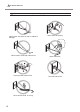
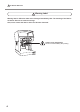
6-1 What to Do If Installation for METAZA driver is Impossible Back Left If installation quits partway through, or if the wizard does not appear when you make the connection with a USB cable, take action as follows. Right Front Windows 7 1.Connect the machine with the computer via a USB cable, and turn on the machine. 2. If the [Found New Hardware] window appears, click [Cancel] to close it. Make sure that all USB cables connected with the printers except this machine are disconnected. 3.
6-1 What to Do If vices]. 6. In the list, find [Printers] or [Other device], then double-click it. When the model name you are using or [Unknown device] appears below the item you selected, click it to choose it. 7. Go to the [Action] menu, and click [Uninstall]. 8.In "Confirm Device Uninstall" window, select [Delete the driver software for this device.], then click [OK]. Close the [Device Manager]. 9. Detach the USB cable connected to the printer, and the restart Windows. 10. Uninstall METAZA Driver.
6-1 What to Do If 3. From the [Start] menu, click [Control Panel]. From the [Hard-ware and Sound] group, click [Printer]. [Printer] folder opens. 4. Click the model name’s icon you are using. From the [Organize] menu, click [Delete]. The [User Account Control] appears, click [Continue]. 5. A message prompting you to confirm deletion appears. Click [Yes]. 6. In the [Printers] folder, right-click any location where no printer icon is present. From the [Run as administrator] menu, select [Server Properties].
6-1 What to Do If the folder where you want to expand the downloaded file.
6-2 When Moving the Machine Attach the retaining materials to the machine. When moving the machine, be sure to attach the retaining materials. Moving the machine without attaching the retaining materials may result in damage to the machine. Procedure Switching on the power. P. 30, "Switching On the Power" Detach the table (or the center vise). Attach a head cap to the tip of head. Hold the head. Head Head cap Switching off the power. P.
6-2 When Moving the Machine Hold down the Power/Movement button for ten seconds or longer. The head moves as shown in the figure. Power / Movement button Loosen the knob Loosen Knob Lift up the head. Tighten the knob as lifting the head. Tighten Adjust the position of the knob so that its center will come above this marking. Head Lift the head.
6-2 When Moving the Machine Unplug the cables. Attach the retaining materials. The machine is to be secured at three points (with 5 screws). Attach all the retainers and wind up the screws with the provided hexagonal wrench. Hexagonal wrench Screw Screws Retainer Screws Retainer Close the cover and repack the machine in the original package.
6-3 Locations of the Power Rating and Serial Number Labels Serial Number This is required when you seek maintenance, servicing, or support. Never peel off the label or let it get dirty. Power Rating Use an electrical outlet that meets the requirements for voltage, frequency, and amperage given here. Power Rating Use an electrical outlet that meets the requirements for voltage, frequency, and amperage given here.
6-4 Specification Main Unit Specifications Printable material Loadable material size Printing area Resolution Printing direction Printing speed (Default) Interface Power requirements Power consumption Acoustic noise level Operation temperature Operation humidity External dimensions Weight Accessories MPX-90 Gold, silver, copper, platinum, brass, aluminium, iron, stainless steel, etc. (Vickers hardness [HV] of the printing surface must be 200 or less.
116
Please read this Agreement before unpacking the media. Software license agreement Roland DG Corporation (hereinafter referred to as the “Company”) shall grant you a non-transferable, nonexclusive right to use the Software supplied with this Agreement, on the condition that you agree to the following provisions. If you agree to the following provisions, you should unpack the media on which the Software is recorded, or simply click the button or other indicator that you agree to the following provisions.