USER'S MANUAL PC-600 Thank you very much for purchasing the PC-600. • To ensure correct and safe usage with a full understanding of this product's performance, please be sure to read through this manual completely and store it in a safe location. • Unauthorized copying or transferral, in whole or in part, of this manual is prohibited. • The contents of this operation manual and the specifications of this product are subject to change without notice.
For the USA FEDERAL COMMUNICATIONS COMMISSION RADIO FREQUENCY INTERFERENCE STATEMENT This equipment has been tested and found to comply with the limits for a Class A digital device, pursuant to Part 15 of the FCC Rules. These limits are designed to provide reasonable protection against harmful interference when the equipment is operated in a commercial environment.
Table of Contents To Ensure Safe Use .......................................... 2 About the Labels Affixed to the Unit ..... 5 Pour utiliser en toute sécurité ................... 6 À propos des étiquettes collées sur l'appareil ... 9 2-10 Powering Off .................................................... 37 Power Off in Daily Operation .................... 37 When Not Use for a Prolonged Period ....... 37 When Not in Use ........................................ 38 Storing Material ..........................
To Ensure Safe Use About and Notices Used for instructions intended to alert the user to the risk of death or severe injury should the unit be used improperly. Used for instructions intended to alert the user to the risk of injury or material damage should the unit be used improperly. * Material damage refers to damage or other adverse effects caused with respect to the home and all its furnishings, as well to domestic animals or pets.
Do not use with a damaged power cord or plug, or with a loose electrical outlet. Use with any other power supply may lead to fire or electrocution. Do not injure or modify the electrical power cord, nor subject it to excessive bends, twists, pulls, binding, or pinching, nor place any object of weight on it. Doing so may damage the electrical power cord, leading to electrocution or fire. When not in use for extended periods, unplug the power cord from the electrical outlet.
Roll material must be placed at a predetermined shaft position. Use the joining screws to secure the unit to the stand. Failure to do so may result in falling of the roll, leading to injury. Failure to do so may result in falling of the unit, leading to injury. Do not touch the tip of the blade with your fingers. Make sure the power to the unit is off before attempting to replace the separating knife. Doing so may result in injury. Doing so may result in injury.
About the Labels Affixed to the Unit These labels are affixed to the body of this product. The following figure describes the location. Do not allow hands or hair to come near the platen while the carriage is in motion. Do not touch the area around the printing carriage with the hands. Model name Rating label Use a rated power supply. In addition to the NOTICE and symbols, the symbols shown below are also used.
Pour utiliser en toute sécurité Avis sur les avertissements Utilisé pour avertir l'utilisateur d'un risque de décès ou de blessure grave en cas de mauvaise utilisation de l'appareil. Utilisé pour avertir l'utilisateur d'un risque de blessure ou de dommage matériel en cas de mauvaise utilisation de l'appareil. * Par dommage matériel, il est entendu dommage ou tout autre effet indésirable sur la maison, tous les meubles et même les animaux domestiques.
Ne pas utiliser avec une fiche ou un fil électrique endommagé ou avec une prise mal fixée. Une négligence à ce niveau pourrait provoquer un incendie ou une électrocution. Débrancher le fil lorsque l'appareil reste inutilisé pendant une longue période. Une négligence à ce niveau pourrait provoquer des décharges électriques, une électrocution ou un incendie dû à une détérioration de l'isolation électrique. Ne pas essayer de débrancher le fil avec des mains mouillées.
Le rouleau doit être placé quand la barre est en position adéquate. Utiliser les vis fournies pour bien fixer l'appareil sur le support. Une négligence à ce niveau pourrait provoquer la chute du rouleau et causer des blessures. Le non-respect de cette consigne pourrait causer des défauts dans l'appareil entraînant des blessures. Ne pas toucher à l’extrémité de la lame avec vos doigts. S'assurer que l'appareil est hors tension avant d'essayer de remplacer la lame séparatrice.
À propos des étiquettes collées sur l'appareil Ces étiquettes sont collées à l'extérieur de l'appareil. Les dessins suivants indiquent l'endroit et le contenu des messages. N' approchez pas vos mains ni vos cheveux du plateau de travail quand le chariot est en mouvement. Ne touchez pas avec les mains la zone située autour du chariot d' impression.
Chapter 1 - Introduction Chapter 1 - Introduction 1-1 Checking Supplied Items Check the following to make sure that you received all the items that were shipped along with the unit.
Chapter 1 - Introduction 1-2 Set-up and Connections Ground the unit with the ground wire. Failure to do so may result in risk of electrical shock in the even of a mechanical problem. Unpacking, installing, or relocating the unit are operations which must be carried out by two or more persons holding the unit at its bottom surface on the left and right sides. Do not use with any electrical power supply that does not meet the ratings displayed on the unit.
Chapter 1 - Introduction When arranging setup space for the PC-600, make sure you have a space that is at least 1500 mm (59-1/16 in.) wide, 750 mm (29-9/16 in.) in depth, and 1500 mm (59-1/16 in.) in height. Since the material moves during printing and cutting, make sure the unit is placed on a stable, sturdy surface. Also make sure there is nothing that can block the material at both front and rear.
Chapter 1 - Introduction 1-3 Part Names and Functions Front View Printing carriage Front cover This is where a ribbon cartridge is mounted in the cartridge holder and printing is carried out. Opening the front cover during printing or cutting causes operation to be paused. Operation resumes when the front cover is closed. No printing or cutting is performed while the front cover is opened. When the front cover is closed, the unit detects the color and location of the installed ribbon cartridge.
Chapter 1 - Introduction Rear View Sheet Loading Lever Used to raise or lower the pinch rollers when loading or unloading material. Automatic setup is performed by loading material and lowering the lever. Power Connector (AC IN) This connector accepts standard AC power cord. Parallel (centronics) input connector In a parallel configuration, connect the parallel cable here. This cable carries data to your computer.
Chapter 1 - Introduction Operation Panel * "Material setup" refers to the state when material has been loaded and the sheet-loading lever has been lowered.
Chapter 1 - Introduction LED Display List : Lights up : Flashing – : Dark LED state POWER SETUP PC-600 status and operator action CARTRIDGE FRONT DATA BASE ALIGN BUSY HOLDER COVER CLEAR POINT POINT – – – – – – – – – – – – – – The sub power is on. For information about canceling sleep state -> sleep state, see "2-2 Powering On Auto-sleep." The unit is installed in a location outside the operating-temperature range.
Chapter 1 - Introduction 1-4 Installing the DRIVER The screens shown in these steps are for windows 95. These screens may differ in places from the screens for windows 98, but the steps themselves are identical. - To perform printing or cutting from a software application, the appropriate software driver must be installed. - The file Readme.txt on the driver-installation disk contains late-breaking information that is not in the manual. Be sure to read through this file.
Chapter 1 - Introduction Installation 1 Switch on the computer and start windows®. 2 Insert the "PC-600 DRIVER for Windows® 98 / 95" disk included with the unit. 3 Click [Start]. Point to [Settings], then click [Printers]. 4 Double-click the [Add Printer] icon. Double-Click Click 5 Click [Next >] and follow the messages to complete installation of the driver.
Chapter 1 - Introduction Driver Setup Use the driver to choose the output port for data. 1 2 Click [Start]. Point to [Settings], then click [Printers]. Click the right mouse button on [Roland PC-600] and select [Properties]. Click the right mouse Click Click 3 Click the [Details] tab and select a port. Select "LPT1: (Printer Port)". Click If you're using a serial connection, click [Port Settings...] and make the settings for the communication parameters.
Chapter 1 - Introduction Using Help If there is something you're not sure about or don't understand when setting up the driver, you can refer to the help screens for that topic. Available topics include details of the various settings as well as the "Printing and Cutting Guide" and "If you Think There's a Problem...." 1 2 Click [Start]. Point to [Settings], then click [Printers]. Click the right mouse button on [Roland PC-600] and select [Properties].
Chapter 2 - Basic Operation Chapter 2 - Basic Operation 2-1 Installing a Blade NOTICE When installing or removing a blade, make sure the sub power for the PC-600 is switched off and no material is loaded. When mounting the blade holder, do not depress the plate slide. Plate slide Do not touch the tip of the blade. This could impair the cutting performance of the blade. To mount the tool holder, insert the tool holder until its collar lies flush against the upper portion of the mounting hole.
Chapter 2 - Basic Operation When cutting is performed after printing, the cap tip of the blade holder may scratch the printed surface. If this is the case, lengthen the cutter blade extension. Removing a Blade 1 2) Remove the blade holder from the cutting carriage. Cutting carriage 2 Pin Blade holder 1) Loosen Tool-securing screw Leave the tool-securing screw loose. Tightening the screw makes it more difficult to install the blade holder.
Chapter 2 - Basic Operation 2-2 Powering On Do not allow hands or hair to come near the platen while the carriage is in motion. Failure to do so may result in injury due to sudden movement of the carriage when the power is switched on/off, when the sheet loading lever is raised or lowered, or when the [CUT TEST] key, [SHEET CUT] key, [DATA CLEAR] key, or [HEAD CLEANING] key is pressed. 1 When using the unit for the first time, switch on the main power switch on the left-hand side of the unit.
Chapter 2 - Basic Operation 2-3 Loading the Material Do not allow hands or hair to come near the platen while the carriage is in motion. Roll material must be placed at a predetermined shaft position. Failure to do so may result in falling of the roll, leading to injury.
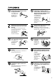
Chapter 2 - Basic Operation 1 * Only when using rolled material Pass the stopper onto the shaft to match the width of the roll material to be used. (The shafts (2 pieces), stoppers (2 pieces), and stopper retaining screws (2 pieces) are included with the stand.) Stopper retaining screws Shaft When fitting the stoppers onto the shaft, loosen the stopper retaining screws and pass the stoppers onto the end of the shaft where the hole is present.
Chapter 2 - Basic Operation Side view of loaded roll material When using a thick roll of material Shafts 4 When only a small amount of material remains (material diameter is 72 mm (2-7/8 in.) or less)... Not OK Shafts Shafts Position so that the left-hand edge of the material lies over any one of the grit rollers. Move the material from side to side and position so that the right-hand edge of the material lies over the rightmost grit roller.
Chapter 2 - Basic Operation 6 Lower the sheet loading levers to secure the material in place. Setup is finished. 7 * Only when using rolled material When the sheet loading lever is lowered, the carriage begins to move. The width of the material is detected, and the carriage stops at the material's right-hand edge. When no setting is made for BASE POINT, the point where the unit stops here becomes the base point.
Chapter 2 - Basic Operation Loadable material widths and pinch-roller positions : Grit roller : Pinch roller (left) : Pinch roller (right) Approx.160 mm (6-1/4 in.) Approx.320 mm (12-9/16 in.) Material Approx.460 mm (18-1/16 in.) Approx.610 mm (24 in.) Position of the pinch roller (left) for material with a width of 610 mm (24 in.) Position of the pinch roller (left) for material with a width of 460 mm (18-1/16 in.) Position of the pinch roller (left) for material with a width of 320 mm (12-9/16 in.
Chapter 2 - Basic Operation To Perform Long Printing/Cutting When performing printing or cutting over a length of 1 m (39-3/8 in.) or more, first feed out the required length of material. Then follow the steps below to load the material. If the setting for enabling the prefeed function has been made on the PC-600, then skip steps 6 and 7. 1 Use material that is wider by 50 mm (2 in.) or more than the width of the printing or cutting to be performed. 3 Position the pinch rollers as shown in the figure.
Chapter 2 - Basic Operation 2-4 Cut Test Do not allow hands or hair to come near the platen while the carriage is in motion. Failure to do so may result in injury due to sudden movement of the carriage when the power is switched on/off, when the sheet loading lever is raised or lowered, or when the [CUT TEST] key, [SHEET CUT] key, [DATA CLEAR] key, or [HEAD CLEANING] key is pressed.
Chapter 2 - Basic Operation 2-5 Installing a Ribbon Cartridge NOTICE Ribbon cartridges must be installed in cartridge holders, and not mounted directly on the printing carriage. Do not allow the marker seals on the ribbon cartridges to be soiled or scratched. Such damage may result in faulty operation. When performing full-color printing, install ribbon cartridges for four colors (CMYK).
Chapter 2 - Basic Operation Installing Ribbon Cartridge 1 2 When installing a new ribbon cartridge, remove the stopper. Take up slack in the in ribbon as shown in the figure. Side B Turn with a pencil or the like - Do not attempt to rewind the ink ribbon. Rewinding the ink ribbon may cause it to break. - A used ribbon cartridge cannot be reused. Do not attempt to turn over and reinstall a used ribbon cartridge, or to rewind the ink ribbon and reuse the cartridge.
Chapter 2 - Basic Operation Replacing an Ink Cartridge If an ink ribbon runs out while printing is in progress, the CARTRIDGE HOLDER LED flashes. Follow the steps below to replace with a new ribbon cartridge. 1 If the ink ribbon runs out, operation stops and the warning beep sounds. (To disable the warning beep, on the machine, set Beep (warning beep for the inkribbon cartridges) to [Disable] (see "3-2 Settings (Making Settings on the PC-600).
Chapter 2 - Basic Operation 2-6 Self-test Do not allow hands or hair to come near the platen while the carriage is in motion. Failure to do so may result in injury due to sudden movement of the carriage when the power is switched on/off, when the sheet loading lever is raised or lowered, or when the [CUT TEST] key, [SHEET CUT] key, [DATA CLEAR] key, or [HEAD CLEANING] key is pressed.
Chapter 2 - Basic Operation 2-7 Downloading Printing/Cutting Date NOTICE When printing a line that is horizontal with respect to the direction of material feed, set the line width to 0.15 mm (0.0059 in.) or more. Printing with a line width less than 0.15 mm (0.0059 in.) may cause the ink ribbon to snap. The unit will begin printing/cutting when it receives printing/cutting data sent from the computer.
Chapter 2 - Basic Operation 2-9 Cutting Off or Detaching the Material Do not allow hands or hair to come near the platen while the carriage is in motion. Failure to do so may result in injury due to sudden movement of the carriage when the power is switched on/off, when the sheet loading lever is raised or lowered, or when the [CUT TEST] key, [SHEET CUT] key, [DATA CLEAR] key, or [HEAD CLEANING] key is pressed.
Chapter 2 - Basic Operation 2-10 Powering Off When not in use for prolonged periods, unplug the power cord from the electrical outlet. Failure to do so may result in danger of shock, electrocution, or fire due to deterioration of the electrical insulation. NOTICE Do not switch off the main power while printing is in progress. Doing so causes the printing head to remain in contact with the sheet, which may damage the head.
Chapter 2 - Basic Operation When Not in Use Place the included dust cover over the machine. This prevents dust from accumulating on the machine and the material. Storing Material When storing material, place it in plastic bags to protect it from dust and grime. Also, do not store material on its side; store is vertically (standing up). If material is placed on its side without wrapping it in plastic, dust and grime may build up on the surface of the material and damage the printing heads when printing.
Chapter 3 - User's Reference Chapter 3 - User's Reference 3-1 Settings for the PC-600 Driver for Windows This sends data to the PC-600 from a Windows-based program. When you are sending data from a commercial draw-type program, make the settings for the cutting parameters with the driver. For a detailed explanation, see the help screens for the PC-600 driver. Displaying the Driver Setting Screen To make the settings for the driver, open Properties.
Chapter 3 - User's Reference Setting the Cutting Parameters At the [Cutting] tab, select the cutting line and make the setting for the cutting speed. Bitmap data is printed, without performing cutting. Make cutting lines using vector data. 1 Choose the cutting method. Specify the cutting line by color or line type. Also, choosing [All] performs cutting for all vector data, and choosing [None] prints all data. 2 Set the movement speed for the blade.
Chapter 3 - User's Reference 3 To use a special color, choose the color to use from [Special], then associate the image color (the color you specified using the program) with an ink ribbon. Install an ink-ribbon cartridge of the color you chose in the PC-600. To print using only special colors, clear the selection for the [Process] item. 4 Choose the type of cartridge. 5 To print a photographic image, select [PhotoColor]. To print a poster image or drawing, select [SpotColor].
Chapter 3 - User's Reference Setting the Operating Parameters At the [Driver Options] tab, make the settings for the machine's operating parameters for other than printing and cutting. 42 1 To use the settings on the PC-600 and not use the driver settings, choose [Enable Machine Settings]. 2 To use the driver settings, choose [Enable Driver Settings] and make the settings for each item. For items with check boxes, select the check box (putting a " " in the check box) to make the setting for [Enable].
Chapter 3 - User's Reference 3-2 Settings (Making Settings on the PC-600) You can make the settings for the following item on the PC-600 itself. Make these settings as required. Auto sheet cut : When this is enabled, the material is separated from the roll when a material-cutting command is sent. Auto-sleep : This sets the interval after which the PC-600 goes to sleep when there is no operation of data processing. When the machine goes to sleep, it enters the power-saving mode.
Chapter 3 - User's Reference Making the Settings 1) Hold down the [ALIGN POINT] key on the panel while you turn the [POWER] key (sub power) on. The ALIGN POINT LED and the POWER LED lights up. and keys changes the displayed CARTRIDGE HOLDER LEDs. 2) Pressing the 3) Referring to the table below, use the and keys to illuminate or extinguish the CARTRIDGE HOLDER LEDs for the value you want to set. 4) The setting is completed when the [POWER] key is used to switch off the sub power.
Chapter 3 - User's Reference 3-3 Other Functions Setting the Base Point – Printing/Cutting at the Desired Location – The BASE POINT key is used to set the base point for printing or cutting. The base point can be set anywhere you like on the material, making it possible to print or cut unused portions of the material. The base point can be set after finishing material setup (and lowering the sheet loading lever). The base point remains enabled until you perform one of the operations described below.
Chapter 3 - User's Reference Setting the Crop Marks, Base Point, and Align Point – Remove the Printed Material, then Reload the Material and Perform Cutting – This feature is for performing position alignment in cases where printing is performed, after which the material removed from the machine for further processing (such as laminating), then again loaded on the machine for cutting. * Setting crop marks to [ENABLE] changes the printing/cutting area.
Chapter 3 - User's Reference 11 Remove the alignment tool from the cutting carriage and install the blade holder. 12 Send the cutting data from the computer.
Chapter 3 - User's Reference Correcting Line Pitch How to Correct Line Pitch 1) Hold down the [BASE POINT] key on the panel while you turn the [POWER] key (sub power) on. The BASE POINT LED and the POWER LED lights up. 2) Pressing the and keys changes the displayed CARTRIDGE HOLDER LEDs. Line pitch: Correct 3) Referring to the table below, use the offset between lines. and keys to determine the amount of 4) The setting is completed when the [POWER] key is used to switch off the sub power.
Chapter 3 - User's Reference 3-5 About the Printing/Cutting Area ..... Printing/Cutting area ..... Crop mark Factory default When front edge sense is enabled 55 mm (2-3/16 in.) 55 mm (2-3/16 in.) Pinch roller (left) Pinch roller (left) 16 mm 68 mm (11/16 in.) (2-11/16 in.) or more 12 mm (1/2 in.) 16 mm (11/16 in.) 68 mm (2-11/16 in.) Pinch roller (right) Pinch roller (right) When crop marks is enabled When crop marks are enabled and a base point has been set 55 mm (2-3/16 in.
Chapter 3 - User's Reference 3-6 About the Blade If the Blade Becomes Dull When the blade starts to lose its sharpness, try gradually increasing the cutter force. Increasing the cutter force temporarily allows the blade to perform better. However, once the blade is dull, it is time to replace it. Average Blade Life The life of a blade varies, depending on the amount of cutting it performs.
Chapter 3 - User's Reference How to Replace the Separating Knife Make sure the power to the unit is off before attempting to replace the separating knife. Do not touch the tip of the blade with your fingers. Doing so may result in injury. Doing so may result in injury. If the separating knife, replace it with the replacement blade included with the PC-600. Follow the steps below to replace the blade.
Chapter 3 - User's Reference 3-7 Care and Maintenance Do not touch the area around the printing carriage with the hands. Failure to do so may result in burns. NOTICE Be sure to switch off the main power for the PC-600 before attempting to clean the unit and platen or using head cleaner to clean the printing head. Never attempt to oil or lubricate the mechanism. Cleaning the Printing Head The PC-600 automatically performs cleaning of the printing head.
Chapter 3 - User's Reference How to Use the Cleaning Sheet The following details the correct usage of this cleaning sheet. Failure to observe the following points may result in damage to the machine. • Do not use any cleaning sheet that has a damaged surface such as cuts, tears or creases. • The printing head can be damaged by dust.
Chapter 3 - User's Reference 8 Lower the sheet loading lever. If the material is not loaded at the correct location, the SETUP LED flashs at the same time. If this happens, reload the material at the proper location. 9 When the front cover is closed, the BUSY LED flashes and head cleaning starts. Head cleaning is finished when the BUSY LED goes dark. 10 When cleaning is finished, open the front cover and raise the sheet loading lever. 11 Remove the material. 12 Switch off the sub power.
Chapter 3 - User's Reference Cleaning the Cleaning Pad If the cleaning pad becomes dirty, clean it gently using a commercially available brush (item with soft fibers) or the like. The Cleaning Pad If the cleaning pad on the left edge of the unit's front surface is damaged, the printing head may be destroyed. If the cleaning pad is damaged by a blade or the like, replace it with a new cleaning pad. Continuing to use a cleaning pad that has deteriorated may impair printing quality.
Chapter 3 - User's Reference 3-8 What to Do If... NOTICE If you want to completely stop the operation of the PC-600, press the [POWER] key. If the sub power cannot be switched off, then switch off the main power. In such cases, however, the printing head remains in contact with the sheet, and attempting to pull out the sheet or move the carriage while in this state which may damage the head. If the PC-600 doesn't run...
Chapter 3 - User's Reference Clean, attractive printing is impossible Is the printing head dirty? Clean the printing head (see “ 3-7 Care and Maintenance”). If cleaning will not improve the printing quality, the printing head might reach to the end of its life. Contact your authorized Roland DG Corp. dealer or service center for replacement of the printing head.
Chapter 3 - User's Reference Cartridge detection is incorrect Has a marker seal on a ribbon cartridge become dirty? Wipe off any grime on marker seals. Are ribbon cartridges designed exclusively for the PC-600 being used? Use only exclusive PC-600 ribbon cartridges. Printing or cutting stops before the normal end is reached Has the material been displaced from the sensors at the front or rear? If the material becomes separated from the front or rear sensor during printing or cutting, operation stops.
Chapter 3 - User's Reference Is the brake installed? If the included brake is not attached, then install it (see "2-3 Loading the Material"). If the settings on the machine have been made to set the prefeed function to [ENABLE], then before performing printing or cutting, the length of material required for output is automatically pulled out from the roll, then returned to the rear, where it is left slack. The brake keeps the material from returning to the roll at this time.
Chapter 3 - User's Reference When performing continuous printing, the image quality changes or margins are grimy When you perform continuous printing, image quality may deteriorate, or ink may build up in the margins. This is because the printing heads grow hot and apply more heat than necessary to the ink ribbon. This is especially likely to occur when performing full-color printing of an image with a large printing surface area, or when printing an iron-on decal.
Chapter 3 - User's Reference 3-9 Specifications PC-600 Mechanism Media-movement method, Thermal-transfer serial, Automatic cartridge-changing type Acceptable Media Width 50 to 610 mm (2 to 24 in.) Maximum Work Area 571.6 mm x 24,998 mm (22-1/2 in. x 984-1/8 in.) * This may be restricted by the program Acceptable Media Type Adhesive vinyl, thickness 0.23 to 0.06 mm (0.00906 to 0.00237 in.) Tools Cutter: blade & blade holder. Printing ribbon: thermal transfer ribbon cartridge.
Chapter 3 - User's Reference Interface specifications Parallel Standard Bidirectional parallel interface (compliant with IEEE 1284: nibble mode) Input signals STROBE (1BIT), DATA (8BITS), SLCT IN, AUTO FEED, INIT Output signals BUSY (1BIT), ACK (1BIT), FAULT, SLCT, PERROR Level of input output signals TTL level Transmission method Asynchronous Interface connector Parallel interface connector (in compliance with specifications of Centronics) Signal number Terminal number Signal number SLCT IN
Please read this agreement carefully before opening the sealed package or the sealed disk package Opening the sealed package or sealed disk package implies your acceptance of the terms and conditions of this agreement. If you do NOT accept this agreement, retain the package UNOPENED. (This product is just one of included items. Please be aware that any amount of the purchase price will not be refunded for return of this product as a single item, regardless of whether the package is opened or unopened.