Owner's Manual Before using this unit, carefully read the sections entitled: "IMPORTANT SAFETY INSTRUCTIONS" (p.2), "USING THE UNIT SAFELY" (p. 4), and "IMPORTANT NOTES" (p. 6). These sections provide important information concerning the proper operation of the unit. Additionally, in order to feel assured that you have gained a good grasp of every feature provided by your new unit, Owner's Manual should be read in its entirety. The manual should be saved and kept on hand as a convenient reference.
WARNING: To reduce the risk of fire or electric shock, do not expose this apparatus to rain or moisture. CAUTION RISK OF ELECTRIC SHOCK DO NOT OPEN ATTENTION: RISQUE DE CHOC ELECTRIQUE NE PAS OUVRIR CAUTION: TO REDUCE THE RISK OF ELECTRIC SHOCK, DO NOT REMOVE COVER (OR BACK). NO USER-SERVICEABLE PARTS INSIDE. REFER SERVICING TO QUALIFIED SERVICE PERSONNEL.
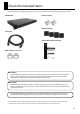
Check the included items The following items are included. Please make sure that all items are present. If anything is missing, please contact your dealer. S-MADI itself Ferrite core (two) fig.S-MADI-itself.eps fig.ferrite-core.eps Rubber foot (four) fig.rubber-foot.eps Power Cord fig.AC-cord.eps Owner’s Manual (this document) fig.owners-manual.eps REAC connector cover (two) fig.connector-cover.
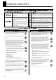
USING THE UNIT SAFELY The symbol alerts the user to important instructions or warnings.The specific meaning of the symbol is determined by the design contained within the triangle. In the case of the symbol at left, it is used for Used for instructions intended to alert the user to the risk of death or severe injury should the unit be used improperly. Used for instructions intended to alert the user to the risk of injury or material damage should the unit be used improperly.
USING THE UNIT SAFELY 015 • 101a Do not force the unit’s power-supply cord to share an outlet with an unreasonable number of other devices. Be especially careful when using extension cords—the total power used by all devices you have connected to the extension cord’s outlet must never exceed the power rating (watts/amperes) for the extension cord. Excessive loads can cause the insulation on the cord to heat up and eventually melt through. ................................................................
IMPORTANT NOTES Power Supply Additional Precautions 301 • Do not connect this unit to same electrical outlet that is being used by an electrical appliance that is controlled by an inverter (such as a refrigerator, washing machine, microwave oven, or air conditioner), or that contains a motor. Depending on the way in which the electrical appliance is used, power supply noise may cause this unit to malfunction or may produce audible noise.
Contents Power Supply ..................................................................................................8 About Cord Hook .................................................................................................................................................... 8 Turning the Power On and Off.......................................................................9 Turning the Power On.....................................................................................................
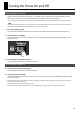
Power Supply Connect the included power cord to AC INPUT connector on rear panel. Be sure to use the included power cord for AC connection. fig.ACconnection.eps AC cord Be sure to connect the power plug only to a power outlet that meets the specifications given on the rating plate. The rating plate is located on the side of the unit. If it cannot easily be checked on the installed unit, refer to “Main Specifications” (p. 27).
Turning the Power On and Off Turning the Power On Once the connections have been completed (p. 8), turn on power to your various devices in the order specified. By turning on devices in the wrong order, you risk causing malfunction and/or damage to speakers and other devices. * This unit is equipped with a protection circuit. A brief interval (a few seconds) after power up is required before the unit will operate normally.
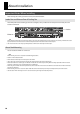
About Installation Important Notes When Installing When installing the S-MADI, give attention to the points described below. Intake Port and Exhaust Port of Cooling Fan The S-MADI performs forced cooling by means of a cooling fan, and is provided with an intake port and a exhaust port at the locations shown below. fig.intake-exhaust.eps Intake Exhaust Never obstruct the intake port or exhaust port.
About Installation About Rubber Feet Attach the included rubber feet as required at the locations shown in the figure below. fig.rubber-foot-location.eps UNIT : mm When mounting the unit in a rack, be sure to detach the rubber feet. Other Notes for Installation * When turning the unit upside-down, get a bunch of newspapers or magazines, and place them under the four corners or at both ends to prevent damage to the buttons and controls.
Part Names and Functions Front Panel fig.front-panel.eps 1 2 3 4 5 1. CLOCK SOURCE Indicator and SELECT Button 6 7 8 9 4. MADI STATUS Indicator These set and display the sampling-clock source. Press the [SELECT] button to choose one of the clock sources described below. The indicator for the currently selected source lights up. REAC This displays the status of MADI input and output.
Part Names and Functions 6. REAC SPLIT OUT Indicator and SELECT Button These set and display the source of the signal coming out from the REAC SPLIT OUT connector. Press the [SELECT] button and choose one of the sources described below. REAC IN This sends (thru-out) the signal coming in from the REAC MAIN connector. MADI IN This converts the signal coming in from the MADI IN connector to a REAC signal and outputs it.
Part Names and Functions Rear Panel fig.rear-panel.eps 1 2 3 4 1. AC IN Connector and Cord Hook This is for connecting the included power cable. Use the cord hook to secure the connected power cable in place (p. 8). 2. REAC SPLIT OUT Connector and Indicator This connector is exclusively for output to REAC devices. The indicator flashes when communication with a connected REAC device has been established. It lights up steadily during standby.
Part Names and Functions 10. WORD CLOCK Connectors and 75 ohm Switch These are connectors for word-clock input and output. You can connect a word-clock generator or other such external device to the WORD CLOCK IN connector for use as the sampling-clock source device. * The signal re-generated from the source (selected as CLOCK SOURCE on the front panel) is output from the WORD CLOCK OUT connector. * To terminate the input for WORD CLOCK at the S-MADI, set the 75 ohm switch to [ON].
Operating the SELECT Buttons Press the [SELECT] buttons to change the mode of the S-MADI. The operation of the [SELECT] buttons is described below. * We are using CLOCK SOURCE selection as an example here. The same procedures are applicable to SAMPLE RATE, REAC MAIN and REAC SPLIT OUT selections. When PANEL LOCK switch is set to [LOCK], the SELECT buttons cannot be operated. To enable operation, set it to [UNLOCK]. 1. Check the current mode. The indicator for the currently selected mode is lighted up.
Connecting External Devices Before Making MADI/REAC Connections Connected Channels for MADI and REAC You can input up to 64 channels to the MADI IN connectors on the S-MADI. The connected channels vary depending on the settings of the CH OFFSET and CH MODE switches, and the REAC SPLIT OUT setting. You can make the settings from 1 through 6 shown below. fig.channel-chart.
Connecting External Devices About Connection Cables Observe the following points with respect to the cables used for connections. • Never use cables with damaged or torn coverings. • Never step on cables or subject them to undue stress. • Never wind cables too tightly or bend them double. Along with the points just described, also observe the following points for specific cable types. Coaxial Cables (75 ohm, BNC connectors) • No single cable should be longer than 100 meters.
Connecting External Devices Connecting MADI/REAC Devices Connection Example 1 : Connecting Digital Snake and MADI Device This sets up a digital snake as a stage unit and connects, via the S-MADI, a digital mixer equipped with MADI input and output. (This performs mutual MADI and REAC conversion.) Connect the stage unit (in this figure, an S-4000S-3208) to the REAC MAIN connector on the S-MADI.
Connecting External Devices Connection Example 2 : Dividing Output from a MADI Device to M-48 units You can configure a system that adds an M-48 live personal mixer to a live mixing system that has MADI output. You can also position an M-48 at Front of House for use as an output device providing monitor sound. Signal routing to the M-48 units on stage is performed by the S-4000D (splitter and power distributor). Connect the S-4000D at stage side to the REAC MAIN connector on the S-MADI.
Connecting External Devices Connection Example 3 : Connecting a V-Mixer As a Monitor Console You can add a V-Mixer to the system in “Connection Example 1” for use as a monitor console. Connect the REAC A connector on the V-Mixer to the REAC SPLIT OUT connector on the S-MADI, and connect the REAC B connector to the S-4000D. * When these connections are made, you can make settings of M-48 remotely from the V-Mixer.
Connecting External Devices Connection Example 4 : Long-distance Transmission of Optical Signals (1) Using an optical cable for the MADI connection enables long-distance transmission. In situations such as when the recording room is located away from the Front of House or you are transmitting audio from a hall/stadium to an outside broadcasting van or the like, use optical cables. * Some MADI recorders require dedicated MADI interfaces for connection with external equipment.
Connecting External Devices Connection Example 5 : Long-distance Transmission of Optical Signals (2) “Connection Example 4” is for recording a concert or the like, but as shown below, you can also make connections that do not go through a mixer. When you record the sound only, with no speaker output, place the digital snake near the sound sources and connect the recorder via the S-OPT units and S-MADI.
Connecting External Devices Connection Example 6 : Configuring a 64-channel Input/Output System Using Two S-MADI Units You can configure a system having 64 inputs and 64 outputs by linking two S-MADI units and connecting S-4000S units to each one. * When the connections shown here are made, the following four types of input/output configurations for the S-4000S become necessary.
Connecting External Devices When making connections described here, set the modes and switches as shown below. Note that the first S-MADI (at the top of the figure) and the second S-MADI (at the bottom of the figure) have different CH OFFSET settings. fig.mode-set6.eps 1st (upper) MADI MASTER MADI IN 1-40 2nd (lower) 41-56(64) 64CH BNC * When CLOCK SOURCE is set to [MADI] or [WORD CLOCK], the S-MADI is automatically set to be the REAC master device.
About the Remote Controller Notes for Serial Connections * Use the accessory RS-232C cable of S-4000R for connection. If it's necessary to use longer or shorter cable, please purchase RS-232C cable (D-Sub 9pins/male-female/ straight type). * It is recommended to use a cable of 15 meters or shorter. * Connect S-4000R or computer to S-MADI, not to Digital Snake.
Appendices Main Specifications fig.spec-sheet.eps Signal Processing Others Network Latency 450 microseconds (AD - S-MADI - DA : about 2.8 ms) Frequency Tolerance +/- 40 ppm Power Supply AC 115 V, 117 V, 220 V, 230 V, 240 V (50/60 Hz) MADI Channel Mode 64 ch / 56 ch Power Consumption 0.7 A : AC 115 V, 117 V 0.6 A : AC 220 V 0.5 A : AC 230 V, 240 V Dimensions 482.0 (W) x 302.7 (D) x 44.0 (H) mm 19 (W) x 11-15/16 (D) x 1-3/4 (H) inches Weight 3.
Appendices Dimensions fig.dimension.eps UNIT : mm 281.5 302.7 430.1 482 465 10.3 ) (R 28 6.
Memo Memo 29
Memo Memo 30
For EU Countries This product complies with the requirements of EMCD 2004/108/EC and LVD 2006/95/EC. For the USA FEDERAL COMMUNICATIONS COMMISSION RADIO FREQUENCY INTERFERENCE STATEMENT This equipment has been tested and found to comply with the limits for a Class B digital device, pursuant to Part 15 of the FCC Rules. These limits are designed to provide reasonable protection against harmful interference in a residential installation.