Owner's Manual Before using this unit, carefully read the sections entitled: “USING THE UNIT SAFELY” and “IMPORTANT NOTES” (Owner’s Manual p. 3-4; p. 5). These sections provide important information concerning the proper operation of the unit. Additionally, in order to feel assured that you have gained a good grasp of every feature provided by your new unit, Owner’s Manual should be read in its entirety. The manual should be saved and kept on hand as a convenient reference.
USING THE UNIT SAFELY The symbol alerts the user to important instructions or warnings.The specific meaning of the symbol is determined by the design contained within the triangle. In the case of the symbol at left, it is used for Used for instructions intended to alert the user to the risk of death or severe injury should the unit be used improperly. Used for instructions intended to alert the user to the risk of injury or material damage should the unit be used improperly.
USING THE UNIT SAFELY 012b • Immediately turn the power off, remove the AC adaptor from the outlet, and request servicing by your retailer, the nearest Roland Service Center, or an authorized Roland distributor, as listed on the “Information” page when: • The AC adaptor, the power-supply cord, or the plug has been damaged; or • If smoke or unusual odor occurs • Objects have fallen into, or liquid has been spilled onto the unit; or • The unit has been exposed to rain (or otherwise has become wet); or • The
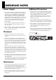
IMPORTANT NOTES Power Supply Additional Precautions 301 • This unit allows you to switch images sat high speed. For some people, viewing such images can cause headache, nausea, or other discomfort. Do not use this unit to create video that might cause these types of health problems.Roland Corporation will accept no responsibility for any such health problems that may occur in yourself or in viewers.
Contents Check the included items..................................................................................................................... 7 Names of Things and What They Do................................................................................................... 8 Top Panel ..................................................................................................................................................... 8 Rear Panel ....................................................
Check the included items The following items are included. Please make sure that all items are present. If anything is missing, please contact your dealer. LVS-800 itself fig.LVS800-itself.eps RCA-BNC adaptor plugs (four) fig.RCA-BNC-plug.eps Owner’s Manual (this document) fig.owners-manual.eps AC Adaptor (PSB-7U) and Power Cord fig.PSB-7U.
Names of Things and What They Do Top Panel fig.top-panel.eps 1 3 2 12 4 13 5 14 15 6 16 17 7 8 1. V-LINK Button This allows connection of V-LINK-compatible equipment from Roland. To operate the RSS-V-Mixer by remote control, press this button to switch it on. What’s V-LINK? V-LINK is a feature for performing video synchronized to music using MIDI. The V-LINK feature provides a quick and simple way to establish a link with a Roland instrument, musicproduction device, or video presenter.
Names of Things and What They Do 6. A Bus/PGM Input Selectors (p. 16) These select the video to input to A Bus. *During use in the PGM-PST mode, you use these to select the video channel for program output. 7. B Bus/PST Input Selectors (p. 16) These select the video to input to B Bus. *During use in the PGM-PST mode, you use these to select the video for preview output. 8. TRANSITION Buttons for A/B MIX (p. 16) These select the transition effect used during a transition between A Bus and B Bus. 9.
Names of Things and What They Do Rear Panel 1 2 3 4 5 6 7 8 9 10 1. PGM PVW Connector This outputs the DSK preview picture. Before performing DSK composition, you connect a monitor to check and verify the video displayed as the DSK foreground. You can then composite the background picture after first checking the logos, text, or other images. 2. PGM OUT Connectors 11 12 13 7.
Connecting Peripheral Devices Connecting Source Devices To prevent malfunction or damage to video monitors or other devices, always turn off the power on all devices before making any connections. Connecting Video Devices Channels 1 through 4 are exclusively for composite signals. S-Video can be connected to channels 5 through 8. Channels 5 and 6 can be used either for composite or S-Video, but S-Video takes priority when both types of signals are input.
Connecting Peripheral Devices Connecting Output Devices The Difference Between A/B MIX OUT and PGM OUT The LVS-800 is equipped with two sets of output connectors. These are the A/B MIX OUT connectors and the PGM OUT connectors. The A/B MIX OUT connectors output only the results of the mixed video of A Bus and B Bus (A/B MIX). The PGM OUT connectors output the results of the A/B mix plus your composited logos, text, etc (DSK composition). Final output fade is enabled only for PGM OUT.
Connecting Peripheral Devices Connecting Output Devices You can connect displays or capture devices to the A/B MIX OUT in order to view or capture the output of the A/B mix only (no DSK). You should connect displays or capture devices to the PGM OUT jacks in order to view or capture the final mix of A/B mix plus DSK. You can connect source monitors to the MONITOR OUT jacks to have at-a-glance monitoring of all your input sources.
Turning the Power On/Off Connecting the AC adaptor Connect the AC adaptor to LVS-800. Place the AC adaptor so the side with the indicator (see illustration) faces upwards and the side with textual information faces downwards. The indicator will light when you plug the AC adaptor into an AC outlet. fig.connect-PSB7U.
Turning the Power On/Off Turning the power on *Once the connections have been completed (p. 14), turn on power to your various devices in the order specified. By turning on devices in the wrong order, you risk causing malfunction and/or damage to monitors and other devices. *This unit is equipped with a protection circuit. A brief interval (a few seconds) after power up is required before the unit will operate normally. Turning the power on Make sure that the AC adaptor is correctly connected.
Switching Between A Bus and B Bus Input sources are selected and switched between the A Bus and the B Bus. The unit has eight input selectors for each Bus, and you choose the input video for each bus before you perform the transition. With the LVS-800, you can switch between A Bus and B Bus in three different modes. Operation of each of these modes is described below. •A/B mode This performs switching using the video fader or the [AUTO] button for A/B MIX.
Switching Between A Bus and B Bus 3. Move the video fader. Move the video fader. Moving it toward the back of the unit makes more of the picture on A Bus appear, and moving toward the front displays more B Bus picture. *If you selected [CUT] in step 2, the picture is switched between A Bus and B Bus at the middle position of the video fader. *When the same input channel has been selected for A Bus and B Bus, moving the video fader does not affect the output. fig.move-Tbar.
Switching Between A Bus and B Bus Switching Using the AUTO Button You can also perform switching simply by pressing the [AUTO] button for A/B MIX, without using the video fader. The video fader itself does not move, but movement between A and B is performed automatically. The location of the light on the TRANSITION indicator shows the movement between A and B. 1. Choose the type of transition (transition effect).
Switching Between A Bus and B Bus Use in Other Operation Modes Besides the A/B Mode Changing the Operation Mode Changing the operation mode is accomplished using the menus. For more information about how to do this, refer to “Changing Settings Using the Menus” (p. 36). *The on-screen menu will only appear on a monitor connected to the A/B MIX PVW jack. 1. From the menu, select “Panel Mode Setup.” Press the [MENU] button to display the menu screen.
Switching Between A Bus and B Bus Switching After Monitoring the Preview Picture (PGM-PST Mode) In the PGM-PST mode, before you perform a switch, you can check the video on the preview monitor, then use the buttons to execute the transition. The preview picture is displayed on the preview monitor connected to the A/B MIX PVW connector. 1. Choose the type of transition (transition effect). If you want to apply a transition effect, use a [TRANSITION] button to choose [MIX], [WIPE1], or [WIPE2].
Switching Between A Bus and B Bus Switching the Picture Directly (LVS Mode) When no previewing is needed, you can perform switching by using only the input selector buttons. This lets you execute a transition more easily and rapidly. You can do this in the LVS mode. In the LVS mode, B Bus is handled as main video and A Bus is handled as insert video. Moving the video fader to the A Bus side superimposes the insert video selected on A Bus over the main video of B Bus.
Switching Between A Bus and B Bus Using Picture-in-Picture to Composite Two Screens You can apply Picture-in-Picture to create a small window of one source superimposed over another source. Composition in the A/B Mode or LVS Mode The A Bus video is the inset screen, and is displayed over the B Bus video (the background). 1. Choose the picture to display in the inset screen. Choose the channel of the video to display in the inset screen on A Bus. fig.select-Ach.eps 2.
Switching Between A Bus and B Bus 4. Move the video fader to the A Bus (inset screen) side. Move the video fader to the A Bus side. The inset screen appears. *The way the inset screen comes into view differs according to the transition-effect setting. When [CUT] has been selected, it remains hidden until the middle position is reached, and is displayed thereafter. fig.move-Tbar-A.eps 5. Move the video fader to the B Bus (background) side. Move the video fader to the B Bus side.
Switching Between A Bus and B Bus Composition in the PGM-PST Mode You can use Preview to check the video for inset-screen display first, then display it using the [AUTO] button. 1. Choose the background channel. Choose the channel of the video to display as the background with PST. fig.select-Ach.eps 2. Display the background. Press the [AUTO] button to display the background video. fig.select-Bch.eps 3. Check the picture of the inset screen.
Switching Between A Bus and B Bus 4. Press a [P in P] button. Press any of the four [PinP] buttons. The location where the inset screen is displayed varies depending on the button you press. The [A] in the square on the panel indicates the location of the inset screen. fig.PinP-button.eps 5. Display the inset screen. Press the [AUTO] button for A/B MIX to composite the inset-screen picture on the background.
Using the Downstream Keyer (DSK) What’s a Downstream Keyer (DSK)? A Downstream Keyer (DSK) allows you to superimpose text or graphics over background video. Since the text of graphics appear “downstream“ from your A/B mix, you can freely switch or mix various video sources behind your “keyed“ text or graphics. Generally, elements such as logos and text are composited using DSK.
Using the Downstream Keyer (DSK) Trying Out DSK Composition 1. Choose the background picture. Use the three BACKGROUND buttons to choose the background video. If you want to use the results of the A/B mix as the background, press the [A/B MIX] button to make it light up. If you want to use source video directly from channel 6 or channel 7 as the background, choose [6] or [7/PC1]. fig.background-select.eps 2. Choose the foreground picture.
Using the Downstream Keyer (DSK) 4. Perform composition and output. Pressing the [AUTO] button for DSK performs composition of the selected FOREGROUND picture superimposed on the selected BACKGROUND picture. The composited video is output to a projector or other device connected to the PGM OUT connectors. fig.DSK-AUTO.eps 5. Adjust the key level. You can adjust the key level by turning the [KEY LEVEL] dial.
Using the Downstream Keyer (DSK) Combining DSK and Picture-in-Picture With the LVS-800, you can perform DSK composition, then also apply Picture-in-Picture (PinP). This lets you display logos or other elements in smaller size and at the place you want on the screen. For information on how to select the background and foreground video, refer to the previous section.
Applying Fade to the Final Output You can apply fade-in or fade-out to the output from the PGM OUT connectors (the program output). Pressing the [AUTO] button for PGM OUTPUT FADE makes the button’s LED flash and starts a fade-out. When the fadeout has been completed, the button stops flashing and stays lit. Press the PGM OUTPUT FADE button again to start a fade-in. When the fade-in ends, the LED goes dark. fig.out-fade-button.
Saving Settings to PANEL PRESET Buttons You can save the state of various controls to [PANEL PRESET] buttons. Saving lets you call up a variety of settings at the press of a button. The [PANEL PRESET] buttons are numbered from 1 to 12, and let you save up to 12 sets of settings. You can save the state of the controls described below. fig.preset-parameter.
Saving Settings to PANEL PRESET Buttons Copying Saved Settings to Another Button You can copy the settings saved from any Panel Preset button to another Panel Preset button. Use the menus to perform the copy operation. For information on how to use the menus, refer to “Changing Settings Using the Menus” (p. 36). *To view the on-screen menu, you need to have a monitor connected to the A/B MIX PVW jack.
Saving Settings to PANEL PRESET Buttons Exchanging Saved Settings with Another Button You can exchange (swap) the settings saved at any button with the settings at another button. Use the menus to perform the exchange operation. For information on how to use the menus, refer to “Changing Settings Using the Menus” (p. 36). 1. Display the menu. Press the [MENU] button to display the menu. 2. Select “Panel Preset Edit.” From the list that appears, choose “Panel Preset Edit,” then press the [ENTER] button.
Returning to Factory-default State (Factory Reset) This returns various settings to their factory defaults. Executing a factory reset causes all settings and saved values except the following settings to be lost. (Please be aware that settings saved to PANEL PRESET buttons are also lost.) •NTSC/PAL setting (p. 35) •Calibration of the video fader (Video Fader Calibrate A/B) *To view the on-screen menu, you need to have a monitor connected to the A/B MIX PVW jack. 1. At the menu, choose “Factory Reset.
Switching Between NTSC and PAL The LVS-800 can switch to NTSC or PAL at startup. Switching to NTSC at Startup At the DSK section, under [BACKGROUND], hold down the [A/B MIX] and [7/PC1] buttons and turn on the power. Once set to NTSC, the setting persists in memory even after power off. fig.change-NTSC.eps Switching to PAL at Startup At the DSK section, under [FOREGROUND], hold down the [A/B MIX] and [8/PC2] buttons and turn on the power.
Changing Settings Using the Menus Making changes to various settings, including the operation mode and the location and size of the inset screen for Picture-in-Picture, are tasks you perform after first displaying the menus. Displaying the Menus The menus are displayed in the preview monitor connected to the A/B MIX PVW connector. When you’re performing menu operations, first be sure to connect a preview monitor. Pressing the [MENU] button displays the menu screen on the preview monitor. fig.PVW-monitor.
Changing Settings Using the Menus Menu Operations Use the procedure described below to change various settings. 1. Display the menu. Go to SETUP and press the [MENU] button. The menu screen appears on the preview monitor. fig.press-MENU.eps 2. Choose the item whose setting you want to change. Use the up and down arrow buttons to choose the item whose setting you want to change. fig.cursor-button.eps 3. Decide on the setting-change item. Press the [ENTER] button to move down one level. fig.
Menu List Going to SETUP and pressing the [MENU] button starts by displaying the menu items at the first level. For information on the menu items at the second level, refer to the following pages. fig.menu-top.eps MENU Wipe1 Setup This chooses the wipe pattern and other such settings assigned to the Wipe1 button. Wipe2 Setup This chooses the wipe pattern and other such settings assigned to the Wipe2 button. PinP1 Setup This sets the location, size, and the like of the PinP1 inset screen.
Menu List Wipe Setup Menu fig.wipe1-menu.eps MENU Wipe1 Setup Wipe2 Setup 01:FAM Mixes A/B keeping the luminance levels unchanged during the transition. 02:NAM Mixes while showing areas that have high luminance levels during the transition. These are standard wipes. You choose the pattern from the following selections. 03:Wipe01 09:Wipe07 04:Wipe02 10:Wipe08 05:Wipe03 11:Wipe09 06:Wipe04 12:Wipe10 07:Wipe05 13:Wipe11 08:Wipe06 These are soft-edge wipes.
Menu List PinP Setup Menu fig.PinP-menu.eps MENU PinP1 Setup PinP2 Setup PinP3 Setup PinP4 Setup PinPx-Hposi This adjusts the horizontal position of the inset screen. PinPx-Vposi This adjusts the vertical position of the inset screen. PinPx-Size This adjusts the size of the inset screen. PinPx-Border This adjusts the width of the border on the inset screen. PinPx-BColor This selects the border color on the inset screen. PinPx-Shadow This adjusts the width of shadow added to the inset screen.
Menu List PC Input Setup Menu fig.PC-input-menu.eps MENU PC1 Input Setup PC2 Input Setup Hposition This adjusts the display position in the horizontal direction. Vposition This adjusts the display position in the vertical direction. Hsize This adjusts the size in the horizontal direction. Vsize This adjusts the size in the vertical direction. Contrast This adjusts the contrast. Brightness This adjusts the brightness. Sharpness This adjusts the sharpness of the outline.
Menu List Output Fade Menu fig.out-fade-menu.eps MENU Output Fade Black This selects black as the fade color. White This selects white as the fade color. In the factory-default state, this is set to black. Panel Preset Edit Menu fig.Panel-Preset-menu.eps MENU Panel Preset Edit Copy This copies saved values to another number. Exchange This exchanges saved values with another number. Preset Play Select This determines whether each individual item is called up.
Menu List MIDI Setup Menu These settings are required when operating the unit by remote control. fig.MIDI-menu.eps MENU MIDI Setup MIDI Channel This sets the MIDI send and receive channel. MIDI Out/Thru Switch This determines whether output is passed through unchanged. Device ID This sets the MIDI device ID. Input A-BUS Assign This sets the input selection message for Bus A. Input B-BUS Assign This sets the input selection message for Bus B.
Troubleshooting Power Supply The power does not come on when the POWER switch is turned on. • Is an AC adapter other than the included one being connected? Use the included AC adapter (Roland PSB-7U). Video Output No picture is output. • If the PGM OUTPUT FADE button illuminated? No video is output while the output fade button is lighted. “Applying Fade to the Final Output (PGM OUT)” (p.
Troubleshooting Others Menu settings are not saved. • Was the power turned off before you quit the menu display? The values of menu settings are saved in internal memory when you exit the menu. To save the values of settings after making any changes, first quit the menu display before you switch off the power. Settings cannot be saved to a PANEL PRESET. • Do the controls allow their states to be saved? For some controls, saving the current state is not possible.
Main Specifications fig.spec-sheet.eps Video Processing Input Connectors Format NTSC/PAL (ITU601) Sampling 13.5 MHz, 4:2:2 (Y:R-Y:B-Y), 8 bit Frame Synchronizer Built in x 3 RGB Supported RGB Inputs 640 x 480/120 Hz, 800 x 600/120 Hz, 832 x 624/75 Hz, 1024 x 768/80 Hz, 1152 x 864/80 Hz, 1152 x 870/75 Hz, 1280 x 1024/75 Hz, 1600 x 1200/60 Hz Remote Control * Conforms to VESA DMT Ver 1.
Index A A/B MIX OUT ............................................................... A/B MIX PVW ............................................................... A/B Mode ...................................................................... AUTO Button ................................................................. S 10 10 16 18 SETUP ............................................................................... 8 Source ..............................................................................
Memo Memo 48
Memo 49
For EU Countries For China