User’s Manual Thank you very much for purchasing the product. • To ensure correct and safe usage with a full understanding of this product's performance, please be sure to read through this manual completely and store it in a safe location. • Unauthorized copying or transferral, in whole or in part, of this manual is prohibited. • The contents of this operation manual and the specifications of this product are subject to change without notice.
For the USA FEDERAL COMMUNICATIONS COMMISSION RADIO FREQUENCY INTERFERENCE STATEMENT This equipment has been tested and found to comply with the limits for a Class A digital device, pursuant to Part 15 of the FCC Rules. These limits are designed to provide reasonable protection against harmful interference when the equipment is operated in a commercial environment.
Contents Features of the SC-545EX............................................................................4 To Ensure Safe Use ......................................................................................5 Pour utiliser en toute sécurité.....................................................................9 Chapter 1: Getting Started........................................................................15 1-1 Checking Accessories ..................................................................
Contents 2-7 Reloading the Media and Performing Cutting .............................................................................. 55 Printing Area ............................................................................................................................................................. 55 Printing with Crop Marks ......................................................................................................................................... 56 Aligning Automatically .........
Contents 5-5 5-6 5-7 5-8 Disposing of Discharged Ink ........................................................................................................ 91 How to Replace the Blade ............................................................................................................ 92 How to Replace the Separating Knife .......................................................................................... 93 When Moving the Unit .............................................................
Features of the SC-545EX What Is the SC-545EX? The SC-545EX is a large-format printer equipped with a cutting feature and combining high speed with high print quality. Not only can it be used either solely for printing or solely for cutting, but it can also perform printing and cutting simultaneously. Also, using the crop-mark feature lets you remove media after printing, then load it again and perform cutting, positioning it accurately. It also achieves better weatherability through the use of ECO-SOL INK.
To Ensure Safe Use About and Notices Used for instructions intended to alert the user to the risk of death or severe injury should the unit be used improperly. Used for instructions intended to alert the user to the risk of injury or media damage should the unit be used improperly. * Media damage refers to damage or other adverse effects caused with respect to the home and all its furnishings, as well to domestic animals or pets.
To Ensure Safe Use Do not use with any electrical power supply that does not meet the ratings displayed on the unit. Use with any other power supply may lead to fire or electrocution. Ground the unit with the ground wire. Failure to do so may result in risk of electrical shock in the even of a mechanical problem. Use only with the power cord included with this product. Use with other than the included power cord may lead to fire or electrocution.
To Ensure Safe Use Install in a level and stable location. Failure to do so may result in the unit tipping over, leading to injury. Unpacking, and installation must be carried out by four or more persons. Otherwise the machine or the stand may fall, resulting in injury. Use care to avoid pinching the fingers when placing the unit on the stand. Doing so may result in injury. Do not touch the tip of the separating knife with your fingers. Doing so may result in injury.
To Ensure Safe Use About the Labels Affixed to the Unit These labels are affixed to the body of this product. The following figure describes the location and content of these messages. Front Do not place hands within the space to the front of the unit while in operation. Ink and discharged ink are flammable. Keep away from open flame. Ink and discharged ink are toxic. Avoid contact with the body. Use only in a well-ventilated area. Rear Ink cartridge Inside the front cover Do not touch the platen.
Pour utiliser en toute sécurité Avis sur les avertissements Utilisé pour avertir l'utilisateur d'un risque de décès ou de blessure grave en cas de mauvaise utilisation de l'appareil. Utilisé pour avertir l'utilisateur d'un risque de blessure ou de dommage matériel en cas de mauvaise utilisation de l'appareil. * Par dommage matériel, il est entendu dommage ou tout autre effet indésirable sur la maison, tous les meubles et même les animaux domestiques.
Pour utiliser en toute sécurité Ne jamais poser d’objets potentiellement inflammables sur la plaque d’exposition lorsque le chauffage fonctionne. Cela crée un risque d'incendie. Ne pas répandre de liquide combustible sur la plaque d’exposition. Cela crée un risque d'incendie. Ne pas utiliser avec une source d'alimentation électrique non conforme à la norme indiquée sur l'appareil. Utiliser l'appareil avec une autre source d'alimentation risque de provoquer un incendie ou de causer une électrocution.
Pour utiliser en toute sécurité S'assurer que le lieu de travail est bien aéré. Installer sur une surface stable et de niveau. Sinon, des odeurs fortes peuvent se dégager et il y a risque de malaises physiques ou d'incendie. Sinon, l'appareil risque de se renverser et de causer des blessures. Ne pas mettre le liquide nettoyant en contact avec les yeux ou la peau. Ne pas boire ou ni respirer délibérément l'encre ou le liquide nettoyant.
Pour utiliser en toute sécurité Ne pas toucher la plaque d’exposition lorsque le chauffage fonctionne. La plaque étant très chaude, il est possible de se brûler. Ne pas toucher à l’extrémité de la lame avec vos doigts. Une négligence à ce niveau pourrait provoquer des blessures. Ne pas toucher le panneau de commande pendant le nettoyage des têtes ou d’autres pièces. Le chariot d’impression peut bouger et causer des blessures.
Pour utiliser en toute sécurité À propos des étiquettes collées sur l'appareil Ces étiquettes sont collées à l'extérieur de l'appareil. Les dessins suivants indiquent l'endroit et le contenu des messages. Avant Ne pas mettre les mains dans l'espace devant l'élément quand celui-ci est en marche. L'encre et l'encre usée sont inflammables. Les garder loin de toute flamme nue. L'encre et l'encre usée sont toxiques. Éviter tout contact avec le corps. Utiliser uniquement dans un endroit bien aéré.
14
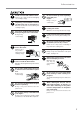
Chapter 1: Getting Started This section describes what to do when you first open the packing carton, including installing the machine and connecting it to a computer.
1-1 Checking Accessories The following items are packed together with the unit. Make sure they are all present and accounted for.
1-2 Part Names Front View Front cover Loading lever Operation panel Cover Cover Rear View Main power switch RJ-45 (Ethernet) connector POWER Power connector Ink cartridge ports Drain bottle Chapter 1: Getting Started 17
1-2 Part Names Inside the Front Cover Cutting carriage Knife guide Pinch roller Print-head carriage Grit roller Cutter protection Media clamp Platen (equipped with the print heater) Operation Panel (1) Display BUSY LED [TOOL UP/DOWN] key [AUTO ALIGN] key [TEST PRINT] key SETUP LED [SETUP] key [CLEANING] key PAUSE LED [PAUSE] key [SHEET CUT] key [TEST CUT] key POWER LED [CUT CONFIG] key [POWER] key [MENU] key [ENTER] key Arrow keys BASE POINT LED [BASE POINT] key ALIGN POINT LED [ALIGN POI
1-2 Part Names Operation Panel (2) Temperature display panel Print-heater power switch The print heater operates only when both the print-heater power switch and the sub power are switched on. [C1] Indicator This indicator lights when the print heater is operating. It goes dark when the temperature reaches the preset temperature and the print heater stops operating. This indicator lights when the print heater is switched on. [SEL] Key Do not press the [SEL] key.
1-3 Assembling and Installing Do not operate in a location exposed to open flame, sparking, or static electricity, or in a location exposed to high temperatures, such as in the immediate vicinity of a heater. Also, do not place undried media in such locations. Doing so may result in fire due to combustion of ink or cleaning liquid. Ensure adequate ventilation for the work area. Failure to do so may result in odor, physical distress, or fire.
1-3 Assembling and Installing Step 1: Assemble the Stand First assemble the stand, then mount the machine on top of the stand. 1 Invert the stand legs as shown in the figure. While supporting the stand legs with your hand, attach the left- and right-hand casters. Tighten the bolts securely. Loose bolts may cause the stand to wobble. Short Hexagonal wrench Long Pipe Bolts (Large) 4 pcs. 4 pcs. 2 Set the stand upright so that the casters are at the bottom, and place the machine on the stand.
1-3 Assembling and Installing 3 Use the included large bolts to secure the machine to the stand. Three places each on the left and right.
1-3 Assembling and Installing Step 2: Install the Included Items 1 Attach the arms onto the back of the machine at the locations shown in the figure. Left-hand side of the back of the unit Right-hand side of the back of the unit Bolts (Large) Bolts (Large) Arm (Right) 2 Arm (Left) Pass the stoppers onto both ends of the shaft. When passing the shaft through the stopper, be sure to loosen the screws on the stopper first. Tighten loosely with the screws.
1-3 Assembling and Installing Step 3: Install the Drain Bottle Leave the drain bottle attached at all times, removing it only when moving the machine or disposing of collected ink. 1 Use the included large bolts to secure the bottle stand in place. Bottle stand Large bolts 2 Remove the stopper from the drain tube. When you remove the stopper from the drain tube, discharged fluid used in shipping inspection may be released from inside the tube. Exercise caution.
1-3 Assembling and Installing 4 Remove BOTH the lid and the inner cover from the drain bottle. Attach the drain bottle to the back of the machine. For more information about how to dispose of discharged ink. ☞ "5-5 Disposing of Discharged Ink" Drain bottle When the level of collected fluid is in this range, detach the drain bottle and dispose of the discharged ink.
1-3 Assembling and Installing Step 4: Remove the Protective Media The protective media shown below is attached to this machine when it is shipped from the factory. When you have finished installing the machine, remove all protective media. Front Packing 1) Remove packings. Packing 2) Peel off the tape. 3) Peel off the tapes, and remove the packings. 4) Peel off the tape, and remove the packing. (Pull straight back toward you to extract.) 5) Peel off the tape.
1-4 Connecting the Cables Use only with a power supply of the same rating as indicated on the unit. Use with any other power supply may lead to fire or electrocution. Ground the unit with the ground wire. Failure to do so may result in risk of electrical shock in the even of a mechanical problem. Use only with the power cord included with this product. Use with other than the included power cord may lead to fire or electrocution.
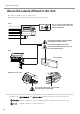
1-4 Connecting the Cables Connecting to the Computer RJ-45 (Ethernet) connector Do not connect a telephone cable to the RJ-45 (Ethernet) connector. Ethernet (10Base-T or 100 Base-TX) Network cable (category 5) Various settings are required when using this machine in a network environment. For more information, see the "RolandPrintServer Network Settings Guide". * Cables are available separately. One which you are sure matches the model of computer being used should be selected.
1-4 Connecting the Cables Securing the Cable Pass the cable through the established location, making sure that it does not touch the loaded media. If the cable touches the media during printing, media feed may be obstructed, resulting in poor printing accuracy. Pass the cable through here.
1-5 Switching On the Power for the First Time Step 1: Install Ink Cartridges Store ink cartridges out of the reach of children. If ink or cleaning liquid comes in contact with the eyes, immediately flush with running water for at least 15 minutes. If an ink cartridge is dropped, the shock due to the fall may damage the ink cartridge and make it unusable. When installing and removing an ink cartridge, do not rush. Detach the cartridge gently. Sudden movement when detaching may cause ink to be spilled.
1-5 Switching On the Power for the First Time Filling Ink Installing ink cartridges for the first time after purchase requires four unused SOL INK cleaning cartridges. This is also the case when you are draining ink in preparation for transport, then reinstalling the ink cartridges. 1 Switch on the main power on the back of the machine. 2 Press the [POWER] key on the operation panel. 3 Check the type of ink to install, then press the [ENTER] key.
1-5 Switching On the Power for the First Time Step 2 : Match the Machine to the Environment Where Installed The machine performs automatic adjustment to optimize its state to the environment where it is used (temperature and humidity). Performing automatic adjustment reduces misalignment in the scanning direction (the direction of movement of the carriage) during printing and cutting. 1 Press the [MENU] key, and press the [ ] key to make the following screen appear on the display.
1-6 Installing the Blade Do not touch the tip of the blade with your fingers. Doing so may result in injury, and the cutting performance of the blade will be impaired. Do not leave the tool mounting screws tightened. Tightening the screw makes it more difficult to install the blade holder. Installing a Blade 1 Push-pin Insert the push-pin into the blade holder. Blade holder 2 Push-pin Insert a blade into the blade holder until it snaps into place with an audible click.
1-6 Installing the Blade 6 Support the tool-securing screw from below and install the blade holder. Insert the blade holder until the collar is flush with the carriage. Be sure to support the tool mounting screw from below when installing the blade holder. Cutting quality may become poor if installed without supporting the screw in this way. 7 Tighten the screw. Tug the blade holder upward to make sure it does not come loose. 8 34 Close the front cover, and press the [ENTER] key.
1-6 Installing the Blade Removing a Blade 1 Press the [MENU] key, and press the [ ] key to make the following screen appear on the display. 2 Press the [ENTER] key to make the following screen appear on the display. MENU REPLACE KNIFE FINISHED ? When the screen shown in the figure appears, the printhead carriage simultaneously moves to the left. 3 Open the front cover, loosen the screw in the figure, and remove the blade holder from the cutting carriage. Screw 4 Remove the blade.
36
Chapter 2: Basic Operation This describes the sequence of basic operations from switching on the power to performing printing or cutting.
2-1 Examples of Operations with This Machine You can perform a wide variety of operations with this machine. For example, you can perform only printing, perform only cutting, or perform printing and cutting, or even perform printing, then remove the media, laminate it, and then cut it. The results of operations such as printing only or cutting only differ depending on the settings used to send the data from the raster image processor (RIP).
2-2 Switching the Power On and Off Switching On the Power Leave the main power switch turned on, and use the [POWER] key to switch the power on and off in day-today use. Points to Keep in Mind When Switching the Power On and Off Do not switch off the main power while the sub power is switched on. The print heads may be left uncapped (that is, the printing carriage may remain over the platen).
2-2 Switching the Power On and Off Switching Off the Power at the End of the Day Press and hold down the [POWER] key for one second or longer to switch off the sub power. Leave the pinch rollers raised when not in use. Deformation may occur if left lowered for a prolonged period.
2-3 Loading Media Be sure to install the shafts when loading roll media. Otherwise the roll may fall and cause injury. Load roll media at the proper position. Otherwise the roll may fall, resulting in injury. Rail portion Do not touch the rail or the inner side of the left and right cover. Touching the area shown may cause the fingers to be soiled by grease or ink, and may result in diminished image quality. Do not put hands inside Loading Roll Media 1 Open the front cover.
2-3 Loading Media 4 Place the rolled media on the shafts. Pass the end of the media between the pinch rollers and the grit rollers so that it extends from the front of the unit. Roll media Shafts 5 When viewed from the front, align so that the left-hand edge of the media is above any of the grit rollers and the right-hand edge is above any of the three grit rollers of the right side of the main unit.
2-3 Loading Media 6 Align the left- and right-hand stoppers with the width of the media and tighten the screws to secure in place. 7 Pull out the media so that at least 50 cm (20 in.) hangs down at the front of the machine. Stopper Screw 8 9 Rotate the media flanges on the shaft to take up the hanging media at the front of the machine. When you roll back the media until the sensor comes into view, a tight seal is formed between the media and the platen, and the media is stretched taut.
2-3 Loading Media 10 Close the front cover. Use the [ ] and [ ] keys to select [ROLL], then press the [ENTER] key. SETUP SHEET ROLL If cutting is to be performed from the edge of the media, select [EDGE] (If [EDGE] does not appear, set [EDGE SENSE] to [ENABLE]). 11 Press the [SETUP] key. This detects the width of the media and displays the printable width.
2-3 Loading Media Loading Sheet Media Before attempting to load sheet media, check the following points. Front View Align the front edge of the media with the location shown in the figure. Front Media Align here. Rear View Remove the shafts and roll media at the back of the unit. Displaying Menu Use the [ ] and [ ] keys to select [PIECE], then press the [ENTER] key.
2-3 Loading Media When Loading Thick Media (Only When Printing) Media that is thick or that warps easily may lead to problems with media feed or jamming. When you are using such media, adjust the height of the print heads. You adjust the height of the print heads only when performing printing. When the height of the print head has been adjusted, it is necessary to perform bidirectional correction.
2-3 Loading Media When Loading Media That Warps Easily (Only When Printing) When you are loading media whose left and right edges are prone to warping, use the media clamps. The media clamps can be used to secure media that is up to 0.7 mm (0.027 in.) or so in thickness. The following media cannot be used even when secured in place by the media clamps.
2-3 Loading Media Separating the Media Make sure the [SETUP] LED lights up. To cut off a printed portion from the roll, hold down the [SHEET CUT] key for at least one second. The piece is cut off at the present location of the printing-start line. This step is not necessary when cutoff is performed automatically by sending a media-cutoff command from the computer. Knife guide Depending on the composition of the media, cutoff may not be possible.
2-4 Printing Do not open the front cover. Opening the front cover while printing is in progress causes an emergency stop. This means that printing may not be carried out correctly even if operation is resumed, due to drop-out or misalignment of the image. During printing, do not touch the portion of the media that's already been discharged. Doing so may obstruct media feed or cause the media to rub against the heads, which may result in a paper jam or damage to the heads.
2-4 Printing Performing a Printing Test Before starting to print, carry out a printing test to check the state of the head. Problems such as missing dots may reduce the printing quality. If the test results show a problem, carry out head cleaning to restore the head to its normal state. 1 Press and hold the [TEST PRINT] key for at least one second to carry out a printing test. The test pattern is printed. 2 If dot drop-out is present, clean the heads.
2-5 Cutting Do not open the front cover. Opening the front cover while cutting is in progress causes an emergency stop. This means that printing may not be carried out correctly even if operation is resumed, due to drop-out or misalignment of the image. Do not use the media clamps during cutting. To Perform Cutting If you're using roll media, then before you start cutting, leave media hanging freely at the rear. Turn the media flanges by hand to pull out the necessary length from the roll.
2-5 Cutting Test Cutting Cutting quality is affected by the blade and media being used, and by the cutting conditions. There are four cutting conditions: "cutting speed", "blade force", "blade offset", and "amount of blade extension". For high-quality cutting, it is necessary to set the appropriate cutting conditions for the blade and media in actual use. The cutting test is a feature for checking beforehand whether these cutting conditions are appropriate.
2-5 Cutting Incorrect cutting conditions may cause symptoms such as those described below. When [CUTTING PRIOR] on the machine's menu has been set to [COMMAND], the program's settings for the cutting conditions take priority. To give priority to the cutting conditions set on the machine, turn off the program settings, or set the [CUTTING PRIOR] menu to [MENU]. For more information about the [CUTTING PRIOR] menu, see the section "6-2 Description of Menus".
2-6 Printing and Cutting You can perform printing and cutting at the same time. You send the data, perform printing, and after printing has finished, you start cutting. Before you send the data, make sure a blade is installed in the cutting carriage. Sequence of Operation for Printing and Cutting Step 1: Perform Printing Step 2: Dry the Media Step 3: Perform Cutting Before you start cutting, allow the media to dry sufficiently. (The drying time varies according to the type of media.
2-7 Reloading the Media and Performing Cutting When you are performing printing, then performing lamination or the like, reloading the media, and performing cutting, using the alignment function makes it possible to align the printing and cutting positions. Alignment of the printing and cutting positions uses crop marks. Printing with crop marks added enables automatic detection of the crop marks during cutting, thereby making alignment possible.
2-7 Reloading the Media and Performing Cutting Printing with Crop Marks Load media and output the data. Crop marks are automatically printed at four places. Use your RIP to make the setting for printing crop marks. For information on how to make the setting, refer to the documentation for the RIP you're using. You can use BASE POINT and ALIGN POINT 1 through ALIGN POINT 3 to perform alignment automatically or manually. For information about how to make the settings, see the following section.
2-7 Reloading the Media and Performing Cutting 3 Use the [ ] and [ ] keys to choose [BASE ALIGN], then press the [ENTER] key. The four crop marks are read automatically. After the reading operation has finished, a beep sounds. 4 AUTO ALIGN BASE - ALIGN Send the cutting data. Cutting starts. If Automatic Alignment Cannot Be Performed If the machine fails to detect the crop marks, the screen shown at right appears and operation stops. If this happens, take action as follows.
2-7 Reloading the Media and Performing Cutting Aligning Manually Depending on the type of media, it may not be possible to detect crop marks automatically. When crop marks cannot be detected automatically, you perform alignment manually. 1 Set the location of the origin point. Use [ ], [ ], [ ], and [ ] to move the center of the blade to above the lower-right crop mark. Use the [TOOL UP/DOWN] key to move the blade up and down and make sure it is positioned correctly. 2 Press the [BASE POINT] key.
Chapter 3: Using the Print Heater This section describes how to print and cut while using the print heater and the like.
3-1 Switching the Print Heater On and Off Switching On the Print Heater 1 Switch on the power switch for the print heater. 2 The [C1] indicator lights up. After the temperature display panel flashes for a short interval, both [SV] and [PV] light up and indicate their values. The print heater starts operating. When the temperature display panel shows characters other than numerical figures, such as UUUU or LLLL, immediately switch off the print heater and contact your authorized Roland DG Corp.
3-2 Loading Media About the Ambient Temperature During Print Heater Use To ensure stable printing quality, we recommend use in an environment where the ambient temperature is 20˚C (68˚F) or higher. At low temperatures, warm-up may take a long time, or the temperature may fail to reach the preset value, or large differences in temperature may occur. Inadequate temperature may result in coarse printing. If the media fails to warm up sufficiently, try setting the print heater to a higher temperature.
3-3 Printing and Cutting Printing Before performing printing, set the preset temperature to 40˚C (104˚F) and wait until media becomes sufficiently warm. The recommended ambient temperature for ensuring acceptable quality when performing printing is 20 to 32˚C (68 to 89.6˚F). When the ambient temperature is less than 20˚C, the media doesn't heat up enough to ensure acceptable quality. In such cases, set the preset temperature to higher value. 1 After loading media, set [SV] to 40˚C.
3-3 Printing and Cutting Cutting/Printing and Cutting Do not use the media clamps during cutting. Assurance of Accuracy When Performing Printing and Cutting When the print heater is used, the media may experience subtle deformation due to thermal expansion or contraction. For this reason, no assurance is made with respect to the following points when the print heater is used.
64
Chapter 4: A Wide Variety of Operations This section describes a wide variety of operations and functions, grouped by task.
4-1 Replacing the Ink Cartridges Care and Handling of Ink Cartridges • Do not use anything other ECO-SOL INK cartridge. Do not attempt to refill and reuse an empty ink cartridge. • Do not attempt to disassemble an ink cartridge. • If an ink cartridge is dropped, the shock due to the fall may damage the ink cartridge and make it unusable. • Store ink cartridges unopened at a temperature of -20°C (-4°F) to 40°C (104°F) in a well-ventilated location.
4-1 Replacing the Ink Cartridges Replacing with New Ink Cartridges Replacing an Ink Cartridge Before you attempt to replace an ink cartridge, check the following two points. • The machine is switched on. • Operation is stopped or paused. Removing or inserting an ink cartridge while operation is in progress may cause air to get inside the cartridge, resulting in poor image quality. 1 Remove the ink cartridge from the ink-cartridge port. Ink cartridge ports 2 Gently shake the new cartridge.
4-1 Replacing the Ink Cartridges If Ink Runs Out During Printing If ink runs out during printing, a warning beep sounds and the screen shown in the figure appears. Replace the ink cartridge. Ignoring the message and continuing printing without replacing the ink may adversely affect image quality, resulting in faintness or other problems. 1_ 2■ 3■ 4 ■ 5■ 6■ 7_ 8■ 9■ 10 ■ 11■ 12 ■ The "_" for the ink that has run out flashes. The number indicates the number of the ink cartridge.
4-2 Checking the Remaining Ink Level You can use [INK REMAINING] on the menu to check how much ink is left after the ink cartridges have been installed. Use this information as a guide for replacing the ink cartridges. In situations such as the following, the installed ink cartridge is taken to be an unused cartridge and the default amount of remaining ink is displayed, which does not match the actual amount of ink remaining.
4-3 Setting the Location Where Printing Starts Setting the Start Location Set the location where printing or cutting starts at the desired place. [ ], [ ], [ ], and [ ] keys and the [BASE POINT] key to set the start points (origin points) for the feed direction (the direction of forward and backward movement) and the scan direction (the direction of movement of the print-head carriage).
4-3 Setting the Location Where Printing Starts Setting the Start Location 1 Load media and install a blade, then press the [SETUP] key. The center of the blade 2 Use the arrow keys to align the blade with the new printing or cutting start location. 3 Press the [BASE POINT] key. The BASE POINT LED lights up The display in the figure appears. W 782 mm B When printing, do not use the [ ] key as much as possible to pulling back the media. Otherwise the following may occur.
4-4 Setting the Margins Setting the Margins in the Feed Direction You can set the margins in the feed direction using the software RIP (raster image processor). For information about how to make the settings for the margins, refer to the documentation for the RIP you're using.
4-5 Making Corrections for Printing Feed Correction This corrects for errors in the amount of feed of the grit rollers due the type of media. Be sure to make this setting when you have replaced the media with a different type. Correcting the amount of feed improves the dot-positioning accuracy in the feed direction, which can help enhance image quality.
4-5 Making Corrections for Printing Bidirectional Correction This adjusts for misalignment that occurs during bidirectional printing. Perform adjustment for bidirectional correction in situations such as the following. • When media is replaced with a different type • When the head height has been adjusted • When using in a location subject to large changes in temperature Bidirectional correction is enabled only when performing bidirectional printing.
4-5 Making Corrections for Printing 6 Press the [ ] key to make the following screen appear on the display. ADJUST BI-DIR SETTING NO.1 You can select from SETTING NO. 1 through SETTING NO. 4. 7 Press the [ ] key to make the following screen appear on the display. 8 Use the [ ], [ ], [ ] and [ ] keys to set the value you checked in step 4, then press the [ENTER] key. H1 0 H1 71/2 H2 8 H3 7 H2 0 H3 0 H4 8 H5 6 H6 7 -30 to +10 (In steps of 1/2) In case of [SETTING NO.
4-5 Making Corrections for Printing Loading an Adjustment Value 1 Press the [MENU] key, and press the [ ] key to make the following screen appear on the display. 2 Press the [ ] key to make the following screen appear on the display. 3 Press the [ ] key to make the following screen appear on the display. 4 Press the [ ] key to display the screen shown in the figure. Choose the memory number to load, then press the [ENTER] key.
4-6 Making Corrections for Printing and Cutting When printing is followed by cutting, the cutting line may be displaced from the printing margin. If this happens, use the [PRINT-CUT ADJ.] function on the menu to align the start points for printing and for cutting. Before you run [PRINT - CUT ADJ.], run [ENV. MATCH]. For more information about how to adjust this, refer to "1-5 Switching On the Power for the First Time" and see "Step 2: Match the Machine to the Environment Where Installed.
4-6 Making Corrections for Printing and Cutting Adjusting Manually Read the correction value from the test pattern printed and cut on the media. Enter the read correction value with the operation panel, then align the printing and cutting positions. 1 Load media and install a blade, then press the [SETUP] key. 2 Press the [MENU] key, and press the [ ] key to make the following screen appear on the display. 3 Press the [ ] key to make the following screen appear on the display.
4-6 Making Corrections for Printing and Cutting 6 Use the [ ] key to choose [FEED SETTING]. 7 Press the [ ] key to make the following screen appear on the display. 8 Enter the correction value read in step 5. Select the correction value with the [ ] [ key, and press the [ENTER] key. 9 Repeat steps 6 through 8 and enter the correction value of [SCAN SETTING]. PRINT - CUT ADJ. FEED SETTING FEED SETTING 0.0 mm 0.
4-7 Stopping Printing or Cutting Operations Stopping Printing or Cutting Operations Stopping Printing or Cutting 1 Press the [PAUSE] key. 2 Halt transmission of printing instructions from the computer. 3 Hold down the [SETUP] key for one second or longer. Any remaining data is cleared. The PAUSE LED lights up The SETUP LED flashes Pausing Printing or Cutting Operations Press the [PAUSE] key. The PAUSE LED lights up. The PAUSE LED lights up To resume printing Press the [PAUSE] key again.
4-8 Recording the Amount of Remaining Media Displaying the Amount of Remaining Media on the Screen You can display how much of the media in use is left. Once you set the amount of media remaining, the amount remaining is displayed at the top menu until it reaches zero. If you cancel the setup such as by removing the media or raising the loading lever, the amount remaining at that time flashes on the screen. * The remaining amount that is displayed is only an estimate, and its accuracy is not assured.
4-9 When Not in Use for a Prolonged Period When the machine is out of use for an extended period, then once a month, switch on the power and perform cleaning. When the machine's main power switch is left on, a warning beep sounds about once a month to remind you to perform cleaning. We recommend switching off only the sub power and leaving the main power on even when the machine is out of use for an extended period.
Chapter 5: Maintenance This section describes how to clean the print heads, daily care and maintenance, and the like.
5-1 Cleaning the Print heads Switching on the sub power automatically performs maintenance operations, including cleaning of the print head. This means that there is normally no need to perform cleaning otherwise. If drop-out occurs with printed images, clean the print head. Cleaning the Print heads 1 Load media for printing-test use. 2 Press the [CLEANING] key, and press the [ ] key to select the printing-head group to clean. Press the [ENTER] key to start head cleaning.
5-1 Cleaning the Print heads If Drop-out Persists Even After Carrying Out Cleaning Several Times Perform head cleaning only when there is dot drop-out (gaps) or printing becomes faint. Performing head cleaning more than necessary subjects the heads to wear and consumes ink. In particular, cleaning performed at the [POWERFUL] menu for [HEAD CLEANING] can cause premature head wear and consume large amounts of ink. 1 Load media for printing-test use.
5-2 Cleaning Using the Cleaning Kit Cleaning using the cleaning kit should be carried out when automatic cleaning and forced cleaning from the [HEAD CLEANING] menu fail to correct image drop-out. Remove any ink buildup of dust or grime around the print heads, which can cause image drop-out or ink drips. We also recommend performing periodic cleaning using the cleaning kit to prevent problems like these during printing.
5-2 Cleaning Using the Cleaning Kit 6 To discharge static electricity from your body, touch the location shown in the figure. 7 Clean the heads and the area around the heads on the left side of the machine. Use a cleaning stick to wipe off any grime from the stainlesssteel frame for the heads and the plastic areas on either side of the heads. Be sure to use one of the included cleaning sticks. Do not touch the nozzle surface of the heads.
5-2 Cleaning Using the Cleaning Kit 10 Wipers Clean the wiper. Use a cleaning stick to wipe away any buildup of dust and grime from the wiper. Replacing the Wiper If the message [REPLACE WIPER] appears on the display, replace the wiper with a new one. As a rule of thumb, the message prompting you to replace the wiper appears when cleaning has been performed 500 times (with [ALL] selected for head cleaning). For information on how to replace the wiper, see "5-3 Replacing the Wiper.
5-3 Replacing the Wiper If the message shown in the figure appears, replace the wiper with a new part. 1 Follow steps 1 through 3 in "5-2 Cleaning Using the Cleaning Kit" to display the screen shown in the figure, and press the [ENTER] key. 2 Follow steps 5 and 6 in "5-2 Cleaning Using the Cleaning Kit" to detach the right cover, and discharge static electricity from your body. 3 Using tweezers, grasp the bottom portion of the wiper and take it off the hook.
5-4 Other Cleaning Tasks When cleaning the unit, be sure to wait approximately 30 minutes or more after switching off the power until the temperature of the platen falls sufficiently. Doing so may cause burns because the platen is hot. Never clean with solvents (such as benzine or thinners). Doing so may cause fire. • When carrying out any cleaning other than cleaning using cleaning sticks, switch off the main power. Before turning off the main power, press the [POWER] key to switch off the sub power.
5-5 Disposing of Discharged Ink The bottle stand for the drain bottle is provided with a window to help determine when discharged ink needs to be disposed. When the discharged ink is within this range, dispose of it. If discharged ink is allowed to exceed this range, it may spill when the bottle is removed. Dispose of ink in the drain bottle as described below. Discharged ink is flammable and contains toxic ingredients. Do not attempt to incinerate discharged ink or discard it with ordinary trash.
5-6 How to Replace the Blade Do not touch the tip of the blade with your fingers. Doing so may result in injury, and the cutting performance of the blade will be impaired. 1 Press the [MENU] key, and press the [ ] key to make the following screen appear on the display. 2 Press the [ENTER] key to make the following screen appear on the display. MENU REPLACE KNIFE FINISHED ? When the screen shown in the figure appears, the printhead carriage simultaneously moves to the left.
5-7 How to Replace the Separating Knife Do not touch the tip of the separating knife with your fingers. Doing so may result in injury. Do not touch the control panel while head cleaning or other cleaning is in progress. The print-head carriage may move and cause injury. If the separating knife becomes dull, replace with the included replacement blade. 1 Press the [MENU] key, and press the [ ] key to make the following screen appear on the display.
5-8 When Moving the Unit Procedures from Preparing to Move Through Reinstalling To move the machine, you must completely drain all ink inside the machine and secure the print heads in place with retainers to protect them. Attempting to move the machine without first doing this may result in damage to internal components due to leaking ink or damage to the heads. This operation requires eight unused SOL INK cleaning cartridges. Have these on hand before you start. Be sure to use SOL INK cleaning cartridges.
5-8 When Moving the Unit 2. Secure the print heads in place. 1 Remove the drain bottle and discard the discharged ink. (Refer to "5-5 Disposing of Discharged Ink.") Pull out the drain tube from the bottle stand and attach the stopper. Stopper 2 3 4 Detach the blade holder. Drain tube Flip the loading lever to the rear. Secure the print heads in place using the retainers. For information on how to secure in place, go to "1-3 Assembling and Installing" and refer to "Step 4: Remove the Protective Media.
96
Chapter 6: Menus and Keys This section contains a flowchart of the menus and describes the operation-panel keys and the menu items.
6-1 Menus Flowchart For details about each of the menus, see the "6-2 Description of Menus." * Selecting the language for screen messages MENU LANGUAGE ENGLISH Roland SC-545EX Ver.1.00 When the power is turned on for the first time, or turned on after removing the ink Roland SC-5405EX ECO-SOL LcLm MENU LANGUAGE JAPANESE Use or to select. Press the [ENTER] key to enable the setting. Roland SC-545EX INK NOT FILLED No ink is filled.
6-1 Menus Flowchart FORCE 50gf 50gf SPEED 40cm/s 30gf to 300gf (In steps of 5gf) 1cm/s to 60cm/s (In steps of 1cm/s) 40cm/s OFFSET 0.250mm 0.250mm UP - SPEED 60cm/s 60cm/s 0.000mm to 1.500mm (In steps of 0.025mm) 1cm/s to 60cm/s (In steps of 1cm/s) Press the [CLEANING] key to perform all head cleaning. CLEANING ALL Press the [ENTER] key to perform head cleaning. CLEANING A GROUP Press the [ENTER] key to perform head cleaning of A Group.
6-1 Menus Flowchart MENU EDGE DETECTION EDGE DETECTION ENABLE ENABLE ENABLE / DISABLE MENU HEAD HEIGHT HEAD HEIGHT HIGH LOW HIGH / MIDDLE / LOW MENU ADJUST BI-DIR ADJUST BI-DIR TEST PRINT ADJUST BI-DIR SETTING NO.1 H1 H2 H3 0 0 0 SETTING No.1/ SETTING No.2/ SETTING No.3/ SETTING No.
6-1 Menus Flowchart [ PRINT & CUT ADJ. ] menu MENU CALIBRATION CALIBRATION PRINTING ADJ. PRINTING ADJ. TEST PRRINT PRINTING ADJ. SETTING SETTING — 0.10% + 0.10% -2.00% to +2.00% (In steps of 0.01%) CALIBRATION CUTTING ADJ. CUTTING ADJ. FEED SETTING FEED SETTING — 0.10% + 0.10% -2.00% to +2.00% (In steps of 0.01%) CUTTING ADJ. SCAN SETTING SCAN SETTING — 0.10% + 0.10% -2.00% to +2.00% (In steps of 0.01%) MENU INK CONTROL INK CONTROL EMPTY MODE EMPTY MODE CONT. STOP CONT.
6-1 Menus Flowchart [ SCAN INTERVAL ] menu MENU VACUUM POWER VACUUM POWER AUTO AUTO AUTO / 0 to 100% (In steps of 10%) MENU PERIODIC CL. PERIODIC CL. DISABLE ENABLE DISABLE / ENABLE MENU UNIT UNIT mm INCH mm / INCH MENU FACTORY DEFAULT MENU SYSTEM REPORT MENU ENV.
6-1 Menus Flowchart [REPLACE KNIFE] menu MENU INK REMAINING MENU SHEET REMAIN MENU HEAD CLEANING 1 5 2 6 3 7 4 8 9 10 11 12 SHEET REMAIN PRINT MEMO SHEET REMAIN SET LENGTH SET LENGTH 0.0 m 0.
6-2 Description of Menus Top menu Submenu Function Setting range Default value EDGE DETECTION — This specifies whether detection of the front and rear edges of the ENABLE/ media is enabled or disabled. DISABLE This should normally be set to [ENABLE]. When loading transparent media, set this to [DISABLE]. When set to [DISABLE], then during media setup only the [ROLL] selection is available. When doing this, ensure a margin of 75 mm (3 in.
6-2 Description of Menus Top menu INK CONTROL Submenu EMPTY MODE PUMP UP HEAD WASH Function Setting range Default value [EMPTY MODE]: When replacement of the ink cartridge becomes [EMPTY [EMPTY necessary while printing is in progress, this setting determines whether MODE] MODE] printing continues or pauses. This setting is used when the ink car- CONT./ STOP tridge cannot be changed immediately during printing, such as durSTOP ing unattended operation at night. [CONT.
6-2 Description of Menus Top menu Submenu Function Setting range Default value PERIODIC CL. — This specifies whether the automatic cleaning during printing is en- D I S A B L E / DISABLE abled or disabled. ENABLE When set to [ENABLE], automatic cleaning is performed during printing, and prevents drop-out and ink drips. Because automatic cleaning is performed during printing, printing may take more time.
6-2 Description of Menus Top menu SHEET REMAIN Submenu SET LENGTH Function Setting range Default value You can display how much of the media in use is left. Once you set the amount of media remaining, the amount remaining is displayed at the top menu until it reaches zero. If you cancel the setup such as by removing the media or raising the loading lever, the amount remaining at that time flashes on the screen. The amount of media remaining is not updated automatically when you change the media.
6-3 Description of Keys Key Top menu Function Default value — This switches on and off the sub power . When the power is switched on, the POWER LED lights up. — — — This detects the presence and the width of the media, and displays the printable width. The SETUP LED flashes while detection of media width is in progress. When setup finishes, the SETUP LED lights up continuously. Also press this key when removing the media.
6-3 Description of Keys Key Top menu Function Setting range Default value — — — This corrects cutting data to align it with printing data that has been output. It is valid only during cutting. — This is used to accept, execute, or save the item shown on the display. — — — Holding down the [TEST PRINT] key for one second or longer while the SETUP LED is lit performs a printing test. — — — This enters the [HEAD CLEANING] menu for cleaning the print heads.
110
Chapter 7: What to Do If... This section describes error messages that may appear on the display and how to resolve problems that can occur during operation.
7-1 What to Do If... The Machine Doesn't Run The Power Does Not Switch On Is the main power switched on? If the power does not come on when you press the [POWER] key, the main power at the back of the machine may not be switched on. Make sure the main power is switched on, then press the [POWER] key again. Printing Doesn't Start When Data Is Sent Are the network settings correct? Make sure there are no errors in the network settings.
7-1 What to Do If... Clean, Attractive Printing Is Impossible If Drop-out Occurs with Printed Images Clean the print heads. (see "5-1 Cleaning the Print heads") The Printed Images Are Not Clean Clean the platen and pinch rollers. (see "5-4 Other Cleaning Tasks") The Print Heads Scrape the Surface of the Media Is the loaded media very thick? If media feed is not smooth because the media catches on the head, then adjust the height of the print heads.
7-1 What to Do If... The Printing Length Is Not Accurate Has feed correction been performed? To correct the amount of feed, refer to "4-5 Making Corrections for Printing" and see "Feed Correction," and make the correction to match the media you're using. During Printing, Ink Drips from the Print-head Carriage and Soils the Media (the printing surface) The following may cause ink to drip on the media during printing. • Dust or fiber-containing grime around the heads may have absorbed ink.
7-1 What to Do If... The Printing and Cutting Positions Are Not Aligned Is the media loaded correctly? If the media is not loaded correctly, the media meanders as it is fed, and the printing and cutting positions become misaligned. Refer to the section "2-3 Loading Media" and load the media correctly. The positions are not aligned even when [AUTO] in [PRINT-CUT ADJ.] is executed. Depending on the type of media, automatic detection of square marks may not be possible.
7-1 What to Do If... The Media Becomes Jammed If [MOTOR ERROR : TURN OFF POWER] Appears and Operation Stops Follow the steps below to clear the error. 1 2 3 4 Press the [POWER] key to switch off the sub power. 5 6 Load the media and carry out setup. 7 Send the printing or cutting data and perform printing or cutting. Remove the jammed media. Cut off any creased or torn portions. Press the [POWER] key to turn on the sub power. Correct whatever caused the media to jam.
7-1 What to Do If... What to Do If the Print-head Carriage Does Not Operate During operation, if for some reason the print-head carriage does not return to the standby position, then following the procedure, cap the print heads, and contact your authorized Roland DG Corp. dealer or service center. If the print-head carriage is allowed to stand for a prolonged period with the print heads uncapped (that is with the printhead carriage over the platen), the heads may become clogged or even damaged.
7-1 What to Do If... 5 When the print-head carriage comes into contact with the caps, rotate the pipe one or two turns more. Make sure the print-head carriage and the caps are touching, then contact your authorized Roland DG Corp. dealer or service center. 118 Chapter 7: What to Do If...
7-2 What to Do If an Error Message Appears Messages Meaning Action CLOSE THE COVER An operation command was given while the cover or front cover is open. Close the cover or front cover. AVOIDING DRY-UP TURN OFF POWER The print head was returned to its standby position to be capped, canceling current printing job. Because emergency stop was effected more than 10 min. Turn power off by pressing [POWER] key to reset. Interrupted printing is not resumed. Repeat printing from the beginning.
7-2 What to Do If an Error Message Appears Messages Meaning Discard discharged ink. * This message appears before operations that will discharge large amounts of ink. There is a chance of discharged ink overflowing if operations are carried out while the drain bottle is full. Remove the drain bottle from this machine, discard the collected ink, then reinstall the drain bottle. Press the [ENTER] key to continue. INSTALL DRAIN BOTTLE Check that the drain bottle is set in position.
7-2 What to Do If an Error Message Appears Messages Meaning Action TEMPERATURE IS TOO HIGH The air temperature where installed is higher than the ambient temperature at which the unit can operate (approx. 40°C (104°F) or more higher). Recovery from this problem is impossible. Use the [POWER] key to switch the power off. First drop the temperature of the area where installed, then switch on the power.
122
Chapter 8: Specifications 123
8-1 Media Conditions Usable Media Use genuine media from Roland DG Corp. Media width 8-5/16 to 54 inches (210 to 1371 mm) A B A) Cuttable media thickness D 0.08 to 0.22 mm (3.2 to 8.6 mil) (depending on media composition) B) Maximum media thickness (including backing paper) Printing only : 1.0 mm (39 mil) When performing cutting : 0.4 mm (15 mil) C) Maximum diameter for roll media 180 mm D) Paper tube (core) inner diameter 50.8 mm or 73.
8-1 Media Conditions Acceptable Media Width 210 to 1371 mm (8-5/16 to 54 in.) Media Approx. 210 mm (8-5/16 in.) Approx. 410 mm (16-1/8 in.) Approx. 405 mm (15-15/16 in.) Approx. 605 mm (23-13/16 in.) Approx. 605 mm (23-13/16 in.) Approx. 805 mm (31-11/16 in.) Approx. 830 mm (32-11/16 in.) Approx. 1030 mm (40-9/16 in.) Approx. 1000 mm (39-3/8 in.) Approx. 1200 mm (47-1/4 in.) Approx. 1171 mm (46-1/8 in.) Approx. 1371 mm (54 in.
8-2 About the Printing or Cutting Area The printing or cutting area along the horizontal plane (the direction in which the carriage moves) is determined by the position of the pinch rollers. The workable area spans the length between the two rollers, minus a margin of about 1.5 mm (about 0.06 in.) on both sides. If "PIECE" has been selected and media length (the distance in the X direction as shown in the figure) is 2,000 mm (783/4 in.), the area is the same as when "EDGE" has been chosen.
8-3 The Media-cutoff Location During Continuous Printing The media-cutoff location that is used when a media-cutoff command is sent from the computer is determined as follows. Start of the next printing operation 75 mm (3 in.
8-4 About Blade Life Cutting conditions and blade life vary according to the hardness of the media and the usage environment. Making the settings for the conditions described below does not automatically guarantee attractive cutting results in all situations. Before performing actual cutting, be sure to carry out a cutting test and make any necessary adjustments.
8-5 Locations of the Power Rating and Serial Number Labels Serial Number This is require when you seek maintenance, servicing, or support. Never peel off the label or let it get dirty. Power Rating Use an electrical outlet that meets the requirements for voltage, frequency, and amperage given here.
8-6 Specifications SC-545EX Printing/Cutting method Piezo ink-jet method/media-moving method Acceptable media widths While the print heater is running 500 to 1371 mm (19-11/16 to 54 in.) While the print heater is not running 210 to 1371 mm (8-5/16 to 54 in.) Printing/Cutting width Ink cartridges Maximum 1346 mm (53 in.
8-6 Specifications *1 • Media type: Roland SV-G-1270G, print travel: 1 m • Preset temperature for the print heater: 40˚C • Temperature: 20˚C, humidity: 50% *2 • Media type: Roland PET-G-1050, print travel: 1 m *3 Not assured when the print heater is used. *4 The following conditions must be satisfied: • Media type: 3M Scotchcal Mastercut Film • Roll media must be loaded on the shaft • The required length for cutting must be pulled out from the roll.
132
R2-041129