Before using the V-60HD, ensure that its system program is at the most recent version. For information on available upgrades for the system program, see the Roland website (https://proav.roland.com/). You can check the system program version by pressing the [MENU] button0“SYSTEM”0“VERSION.” Owner’s Manual (this document) Read this first. It explains the basic things you need to know in order to use the V-60HD.
Contents USING THE UNIT SAFELY. . . . . . . . . . . . . . . . . . . . . . . . . . . . . . . . . . . . . 3 Audio Operations . . . . . . . . . . . . . . . . . . . . . . . . . . . . . . . . . . . . . . . . . . . 24 Adjusting the Volume Level . . . . . . . . . . . . . . . . . . . . . . . . . . . . . . . . 24 Adjusting the Head Amp Gain . . . . . . . . . . . . . . . . . . . . . . . . . . 24 Adjusting the Sound Position (Pan). . . . . . . . . . . . . . . . . . . . . . 24 Adjusting the Volume Balance . . . . . .
USING THE UNIT SAFELY About WARNING and CAUTION Notices About the Symbols The symbol alerts the user to important instructions or warnings.The specific meaning of the symbol is determined by the design contained within the triangle. In the case of the symbol at left, it is used for general cautions, warnings, or alerts to danger. Used for instructions intended to alert the user to the risk of death or severe injury should the unit be used improperly.
USING THE UNIT SAFELY WARNING Be cautious to protect children from injury Always make sure that an adult is on hand to provide supervision and guidance when using the unit in places where children are present, or when a child will be using the unit. Do not drop or subject to strong impact Otherwise, you risk causing damage or malfunction. Do not share an outlet with an unreasonable number of other devices Otherwise, you risk overheating or fire.
IMPORTANT NOTES Power Supply • Do not connect this unit to same electrical outlet that is being used by an electrical appliance that is controlled by an inverter or a motor (such as a refrigerator, washing machine, microwave oven, or air conditioner). Depending on the way in which the electrical appliance is used, power supply noise may cause this unit to malfunction or may produce audible noise.
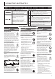
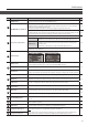
Panel Descriptions Top Panel/Side Panel Side Panel Side Panel 16 17 2 3 8 1 9 5 4 10 12 6 1 2 14 11 7 15 Name NO. 13 17 Explanation COMP/LMT indicators When the compressor is turned on for AUDIO IN 1–5/6, this lights up when compression is applied. p. 26 AUDIO INPUT LEVEL [1]–[5/6] knobs These adjust the volume level for AUDIO IN 1–5/6. p. 25 SIG/PEAK indicators This lights up when input via AUDIO IN 1–5/6 is detected, and when the volume level is too high. p.
Panel Descriptions Name NO. [MODE] button 6 Explanation This switches the functioning of the AUX/MEMORY buttons. When the [MODE] button is lighted in green The buttons function as AUX-bus selection buttons. They select the video (channel 1–8) to send to the AUX bus. The selected button lights up in red. AUX/MEMORY [1]–[8] buttons The respective buttons also function as indicators showing the input status of the video.
Panel Descriptions Rear Panel/Front Panel (Connecting Your Equipment) * To prevent malfunction and equipment failure, always turn down the volume, and turn off all the units before making any connections. * Be sure to use cables and adaptor plugs with the proper connectors matching those of the other devices you are using. DC IN jack SDI OUT 1 and 2 connectors, HDMI OUT 1 and 2 connectors Connect the included AC adapter to this jack.
Panel Descriptions AUDIO OUT connectors/jacks (XLR and RCA) AUDIO IN 5/6 jacks AUDIO IN 1–4 jacks (XLR/TRS) These output the results of audio mixing (master out). Connect them to an audio recording deck, amplifier, speakers, or other such equipment. These jacks input audio signals from video decks, CD players, and other such audio equipment. These jacks input audio signals from microphones, audio mixers, and other such audio equipment.
Panel Descriptions Multi-view Monitor Display A list of input/output video streams, the audio level meter, and the OSD menu are displayed on the multi-view monitor connected to the MULTI-VIEW connector. * Pressing the [MENU] button displays the OSD menu. Its content is the same as the menu shown on the built-in display (p. 11). Label names, tally borders, and the audio level meter are hidden while the OSD menu is displayed.
Basic Operations Turning the Power On and Off * Before turning the unit on/off, always be sure to turn the volume down. Even with the volume turned down, you might hear some sound when switching the unit on/off. However, this is normal and does not indicate a malfunction. Turning the power on Operating the Menu This makes menus appear on the built-in display for making settings for video and audio or for the V-60HD itself.
Video Input/Output Settings Setting the Video Input/Output Format Set parameters for the input/output format to match the connected equipment. Setting the System Format Setting the Input Formats for Channels 5 and 6 On the V-60HD, the input/output format is determined according to the system format. You set the input/output format to match the connected equipment.
Video Input/Output Settings Assigning a Video Source to Channel 6 Adjusting Output Video You can assign a video source at the HDMI IN 6 connector or the RGB/COMPONENT IN 6 connector to channel 6. You change the setting to match the connected source device. You can adjust the output video to match the equipment receiving the output from the V-60HD. * By factory default, the setting is for the HDMI IN 6 connector. You can output a test pattern, useful for adjusting the image quality of a display.
Video Input/Output Settings Adjusting the Input Video This adjusts the image quality of the video input via the respective connectors. For HDMI IN and RGB/COMPONENT IN connectors, you can also adjust the scaling. 1. Select the [MENU] button0“VIDEO INPUT”0the input video. HDMI/RGB IN 6: HDMI IN 6 connector (*2) RGB/COMPONENT IN 6 connector (*2) Menu item Explanation This automatically adjusts the image quality.
Video Input/Output Settings Changing Output Bus Assignments The V-60HD has three internal output buses (PGM, PVW, and AUX). You can select which buses to output via the SDI OUT and HDMI OUT connectors. 1. Select the [MENU] button0“VIDEO OUTPUT”0“SDI OUT 1,” “SDI OUT 2,” “HDMI OUT 1,” or “HDMI OUT 2”0“OUTPUT ASSIGN.” Inputting Copyright-protected (HDCP) Video To input copyright-protected (HDCP) video from a Blu-ray Disc player or the like, follow the steps described below to change the “HDCP” setting.
Video Operations Switching the Video This switches the video that is input into the V-60HD and performs final output. About the Operation Mode for Video Transitions There are two operation modes for switching the video on the PGM/A bus and PST/B bus: the “PGM/PST mode” and the “A/B mode.” By factory default, the operation mode is set to the PGM/PST mode. PGM/PST mode Switching Using the PGM/PST Mode The video on the PGM/A bus is always the final output.
Video Operations 4. Move the video fader in the direction opposite to the direction in step 1. Switching in the A/B Mode The video at the end to which the video fader is flipped is always the final output. 1. Flip the video fader all the way upward or downward. 2. Press a cross-point button at the end to which the video fader is not flipped to select the preset video (the video to output next). Transition indicator The video changes.
Video Operations Switching AUX Output Using Imported Still Images You can use button operations to directly select the video to send to the AUX bus. You can output the video on the AUX bus from SDI OUT connectors or HDMI OUT connectors. To output the AUX bus, you change the bus assignments for the respective connectors to “AUX.” For details, refer to “Changing Output Bus Assignments” (p. 15). 1. Press the [MODE] button to make it light up in green.
Video Operations Importing a Still Image from a USB Flash Drive This imports into the unit a still image saved on a USB flash drive. Supported still-image formats and resolutions Assigning Still Images to Channels 7 and 8 This takes a still image that has been captured or imported from a USB flash drive, and assigns it to channel 7 or 8. 1. Select the [MENU] button0“VIDEO INPUT”0“STILL/BKG 7/8”0“INPUT 7 ASSIGN” or “INPUT 8 ASSIGN.” Still-image file formats that can be imported are as follows.
Video Operations Applying a Fade to PGM/PVW Output Video (Output Fade) This performs a fade-out from the output video to a black screen, or a fade-in from a black screen to the output video. You can insert a black screen into the output video at times where you don’t want to output a picture, such as at intervals in presentations or band performances. MEMO Fade-ins and fade-outs are applied to the final video output (program output) and the preset video (preview output).
Video Composition Operations This composites video. The V-60HD has three built-in types of composition. Compositing Using Picture-in-Picture (PinP) This composites video in an inset screen over a background video. This section describes operations when in the PGM/PST mode (p. 16). Inset screen Background video 1. Press a cross-point button for the PGM/A bus to select the video you want to make the background video. 5. Press the [AUTO] or [CUT] button.
Video Composition Operations Compositing Using Split This composites two video streams in a split screen. The final output video is displayed above or on the left, and the preset video (the video to be output next) is displayed below or on the right. This section describes operations when in the PGM/PST mode (p. 16). Compositing using split 1. Press a cross-point button for the PGM/A bus to select the video you want to display above or on the left. Specifying a split composition pattern 2.
Video Composition Operations Compositing Using DSK This takes video composited upstream using PinP or the like, and performs further downstream compositing with text or images. Using DSK (downstream keying), you can switch the background video while text or images remain displayed. Compositing using DSK 1. Input the logo or image. By factory default, the settings are such that text and image input on channel 6 are used in DSK composition.
Audio Operations Adjusting the Volume Level This adjusts the head amp gain, sound position, and volume balance of audio input to the V-60HD. Adjusting the Head Amp Gain This adjusts the head amp gain so that the input audio is at a suitable level. * You can adjust the head amp gain only for AUDIO IN 1 through 4. 1. Adjust the AUDIO INPUT LEVEL knob for the input audio whose head amp gain you want to adjust to a position near “0 dB.
Audio Operations Adjusting the Volume Balance Outputting AUX-bus Audio This adjusts the volume balance of input and the volume level for master out. 1. Adjust the [MASTER OUTPUT] knob to a position near “0 dB.” 2. While monitoring the audio via speakers or headphones, adjust the volume balance for the respective inputs. Raise the volume level of audio you want to make more prominent, for example, an emcee microphone, and lower the volume level for other audio.
Audio Operations Applying Effects to Audio You can apply effects and adjust the sound quality. Applying Effects to Input Audio This applies effects and adjusts the sound quality for AUDIO IN, SDI IN, and HDMI IN audio. 1. Select the [MENU] button0“AUDIO INPUT”0the input audio. Compressor (COMP/LMT) This compresses audio that exceeds a specified level. 2. Select an effect menu item, then use the [VALUE] knob to adjust it. Menu item Explanation COMP/LMT This sets the compressor on or off.
Audio Operations Applying Effects to Output Audio This applies effects and adjusts the sound quality for master out and AUX-bus audio. * Only the limiter can be used on AUX-bus audio (p. 25). 1. Select the [MENU] button0“AUDIO OUTPUT”0“MASTER OUT” or “AUX.” Equalizer (EQ) * MASTER OUTPUT only This adjusts the sound quality for each frequency band. 2. Select an effect menu item, then use the [VALUE] knob to adjust it. Menu item Explanation EQ Hi This boosts or attenuates the high band.
Audio Operations Controlling Volume Levels Automatically (Auto Mixing) This automatically controls operations that normally are performed by an operator (Auto Mixing feature). It lets you rely on the V-60HD to perform complex volumeadjustment operations, enabling use in circumstances where no dedicated operator is assigned. This is especially useful for meetings, discussions, debates, and other situations where multiple microphones are used.
Audio Operations Interlinking Audio Output to Video Switching (Audio Follow) You can associate audio with a video switch so that when the video is switched, the specified audio alone is output automatically, and other audio is automatically muted. NOTE When the Audio Follow feature is turned on, switching between audio output and muting is carried out automatically. The positions of the controls used to adjust the volume level do not change automatically. 1.
Audio Operations Separating Discrete Analog Input Audio Streams and Adding Them to SDI Video The SDI OUT connectors on the V-60HD accommodate eight channels of embedded audio. In addition to two channels for master out (or the AUX bus), you can separate the six discrete channels of analog input audio (AUDIO IN 1 through 5/6) and add them to SDI video. * The HDMI OUT connectors accommodate two channels of embedded audio (master out or the AUX bus).
Other Features Saving/Recalling Settings (Preset Memory) You can take the current settings, including video and audio settings and the state of the operation panel, and save them as a single set in memory, for later recall and use when needed. The V-60HD is provided with eight preset memories. About the last memory function The V-60HD has a built-in Last Memory feature.
Other Features Saving the Unit’s Settings on a USB Flash Drive You can group together the unit’s settings into a single file (*.V06) and save it to a USB flash drive connected to the USB MEMORY port. You can access the saved file (*.V06) on the USB flash drive and load it into the unit for use when needed. * When you’re using a USB flash drive for the first time, be sure to format it on the V-60HD (p. 33). * Depending on the USB flash drive, recognition of the flash drive might take some time.
Other Features Formatting USB Flash Drives When using a USB flash drive for the first time, be sure to format it on the V-60HD. NOTE 55 The V-60HD does not recognize unformatted USB flash drives. 55 Use a commercially available USB flash drive or a USB flash drive sold by Roland. However, we cannot guarantee that all commercially available USB flash drives will work with this unit. 55 Performing formatting causes all data already saved on the USB flash drive to be deleted.
Other Features Preventing Unintended Operation (Panel Lock) This locks operation of buttons and knobs to prevent unintended operation of the V-60HD. 1. Select the [MENU] button0“SYSTEM”0“PANEL LOCK.” Operating the V-60HD by Remote Control You can operate the V-60HD remotely from an external device. Using the dedicated V-60HD RCS program You can connect the V-60HD to a computer via a LAN or RS-232, and use dedicated program V-60HD RCS to operate the unit by remote control.
Appendices Troubleshooting If you suspect a malfunction, please check the following points. If this does not resolve the problem, contact a nearby Roland Service Center. Problem Items to check Action Page Video-related problems No picture is input. When the [MODE] button is lighted in green, Video in a format that differs from the setting on the V-60HD is being are the AUX/MEMORY buttons flashing in input. Set the system format to match the connected device. green? p.
Appendices Block Diagram Video Section 1080p SYSTEM FORMAT 1080i 720p SDI IN 1 I/P CONV SDI IN 2 SDI IN 3 SDI IN 4 HDMI IN 5 HDMI IN 6 RGB/ COMPONENT IN 6 USB MEMORY FS CAPTURE PGM/A BUS I/P CONV FS CAPTURE 2 I/P CONV FS CAPTURE 3 I/P CONV FS CAPTURE 4 PST/B BUS INPUT SELECT EDID Emu SCALER FS CAPTURE 5 SCALER FS CAPTURE 6 EDID Emu EDID Emu 7 STILL IMAGE 1 STILL IMAGE 2 8 BACKGROUND COLOR PVW MULTI-VIEWER 1 2 5 36 AUX BUS DSK SOURCE BUS 1 6 PGM 3 7 4 8
Appendices COMPOSITION TRANSITION PinP SPLIT WIPE MIX CUT PGM DSK OUTPUT FADE PVW AUX P/I CONV PGM PVW AUX P/I CONV SDI OUT 1 SDI OUT 2 PGM PVW AUX P/I CONV HDMI OUT 1 P/I CONV HDMI OUT 2 PGM PVW AUX MENU OSD 1080p HDMI MULTI-VIEW 37
Appendices Audio Section INPUT BUS L R AUDIO IN 1–4 HEAD AMP GAIN DIGITAL GAIN A/D SIG/PEAK LED HPF 75Hz COMP/LMT LED GATE COMP EQ INPUT MUTE DELAY PHANTOM +48V WET DRY OFF AUDIO IN 5/6 DIGITAL GAIN A/D SIG/PEAK LED L R HPF 75Hz COMP/LMT LED GATE COMP INPUT MUTE EQ WET DRY OFF OFF DIGITAL GAIN CH1 De-embedded HDMI IN 5/6 CH2 De-embedded LEVEL METER L R HPF 75Hz INPUT MUTE GATE COMP EQ AUDIO FOLLOW INPUT LEVEL AUTO MIXING TO “AUDIO IN 5 EMBEDDED” TO “AUDIO IN 6 EMBEDDED
Appendices OUTPUT BUS MASTER OUTPUT L R AUX L R * Same as video output bus CH1 Embedded EMBEDDED CH3–8 ON/OFF FROM “AUDIO IN 1 EMBEDDED” FROM “AUDIO IN 2 EMBEDDED” SDI OUT 1 CH2 Embedded CH3 Embedded CH4 Embedded CH5 Embedded FROM “AUDIO IN 3 EMBEDDED” CH6 Embedded FROM “AUDIO IN 4 EMBEDDED” CH7 Embedded FROM “AUDIO IN 5 EMBEDDED” CH8 Embedded FROM “AUDIO IN 6 EMBEDDED” * Same as video output bus EMBEDDED CH3–8 ON/OFF CH1 Embedded SDI OUT 2 CH2 Embedded CH3 Embedded CH4 Embedded CH5 Embedde
Appendices Main Specifications Roland V-60HD: HD Video Switcher 9 Video Video Processing 4:2:2 (Y/Pb/Pr), 8-bit SDI IN 1–4 Input Connectors HDMI IN 5–6 RGB/COMPONENT IN 6 SDI OUT 1–2 Output Connectors HDMI OUT 1–2 HDMI MULTI-VIEW SDI IN 1–4 *3 Input Formats *1 *2 HDMI IN 5–6 RGB/COMPONENT IN 6 Still Image Output Formats *2 Video Effects SDI OUT 1–2 *3 HDMI OUT 1–2 HDMI MULTI-VIEW Transition Composition Others BNC type x 4 * Conforms to SMPTE 424M (SMPTE 425M-AB), 292M HDMI type A x 2 * HDCP Sup
Appendices Input Impedance Output Level Output Impedance Audio Effects 9 Other Connectors USB MEMORY Tally/GPI RS-232 CONTROL 9 Other Functions AUDIO IN 1–4 10 k ohms (HEAD AMP GAIN 0–23 dB), 5 k ohms (HEAD AMP GAIN 24–64 dB) AUDIO IN 5–6 15 k ohms AUDIO OUT (XLR) +4 dBu (Maximum: +22 dBu) AUDIO OUT (RCA) -10 dBu (Maximum: +8 dBu) PHONES 92 mW + 92 mW (32 ohms) AUDIO OUT (XLR) 600 ohms AUDIO OUT (RCA) 1 k ohm PHONES 10 ohms Auto Mixing, EQ, Delay, Compressor, HPF, Gate, Multi-Band Compressor, Limiter USB
Appendices Transition Effects List MIX Effect Explanation MIX The two pictures are blended together as the video is switched. FAM Video transitions are made with the luminance levels of the two video streams maintained unchanged. * This is an abbreviation of “full additive mix.” NAM The two video streams are compared, and transitions are made with display during transition starting with levels of high luminance. * This is an abbreviation of “non-additive mix.
For the U.K. IMPORTANT: THE WIRES IN THIS MAINS LEAD ARE COLOURED IN ACCORDANCE WITH THE FOLLOWING CODE. BLUE: NEUTRAL BROWN: LIVE As the colours of the wires in the mains lead of this apparatus may not correspond with the coloured markings identifying the terminals in your plug, proceed as follows: The wire which is coloured BLUE must be connected to the terminal which is marked with the letter N or coloured BLACK.
For EU Countries * 5 1 0 0 0 5 7 5 2 6 - 0 2 *