
User Manual


10
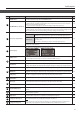
Panel Descriptions
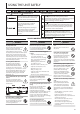
Multi-view Monitor Display
A list of input/output video streams, the audio level meter, and the OSD menu are displayed on the multi-view monitor connected to the
MULTI-VIEW connector.
* Pressing the [MENU] button displays the OSD menu. Its content is the same as the menu shown on the built-in display (p. 11). Label names,
tally borders, and the audio level meter are hidden while the OSD menu is displayed.
21
3
No Name Explanation
1
PVW (preview) section
This displays the preset video (the video to be
output next).
This displays the level meter for master out.
Red (Excessive)
Yellow (Suitable)
Green (Insucient)
(dB)
-30
-20
-6
0
-50
2
PGM (program) section
This displays the nal output video.
3
Channel section
This displays video input via channels 1–6 and still images assigned to channels 7 and 8.
The nal video output and preset video (the video to be output next) are displayed with tally borders.
Channel information
1
2
3
1
When the Audio Follow feature is on (p. 29), the “A.F”
symbol is displayed.
2
When video or a still image is being sent to the AUX bus
(p. 18), the “AUX” symbol is displayed.
3
This displays a level meter for SDI or HDMI audio.
* The indicators for the level meter are the same as for
master out.
MEMO
You can change the settings so that the label names, tally borders, audio level meter, OSD menu, and other such elements displayed on the
multi-view monitor are always hidden.
Select the [MENU] button0“SYSTEM,” then set the menu items shown below to “OFF.”
5 MULTI-VIEW LABEL (label names)
5 MULTI-VIEW TALLY (tally borders and AUX symbol)
5 AUDIO LEVEL METER (audio level meter and A.F symbol)
5 ON SCREEN MENU (OSD menu)