Owner's Manual Before using this unit, carefully read the sections entitled: “USING THE UNIT SAFELY”(p. 4) and “IMPORTANT NOTES” (p. 7). These sections provide important information concerning the proper operation of the unit. Additionally, in order to feel assured that you have gained a good grasp of every feature provided by your new unit, owner’s manual should be read in its entirety. The manual should be saved and kept on hand as a convenient reference.
For the U.K. IMPORTANT: THE WIRES IN THIS MAINS LEAD ARE COLOURED IN ACCORDANCE WITH THE FOLLOWING CODE. BLUE: NEUTRAL BROWN: LIVE As the colours of the wires in the mains lead of this apparatus may not correspond with the coloured markings identifying the terminals in your plug, proceed as follows: The wire which is coloured BLUE must be connected to the terminal which is marked with the letter N or coloured BLACK.
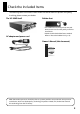
Check the Included Items The following items are included. Please make sure that all items are present. If anything is missing, please contact your dealer. The VC-30HD itself Rubber foot fig.VC30HD-itself.eps fig.rubber-foot.eps * The rubber feet are arranged onto one pad. Remove each one from the pad if you wish to install them. AC adaptor and power cord * Attach the included rubber feet as needed. Refer to “About the Rubber Foot“ (p. 10). fig.PSB1U.eps Owner’s Manual (this document) fig.
USING THE UNIT SAFELY Used for instructions intended to alert the user to the risk of death or severe injury should the unit be used improperly. Used for instructions intended to alert the user to the risk of injury or material damage should the unit be used improperly. * Material damage refers other adverse effects respect to the home furnishings, as well animals or pets. to damage or caused with and all its to domestic 002c • Do not open (or modify in any way) the unit or its AC adaptor. ..............
USING THE UNIT SAFELY 011 • Do not allow any objects (e.g., flammable material, coins, pins); or liquids of any kind (water, soft drinks, etc.) to penetrate the unit. .......................................................................................................................
USING THE UNIT SAFELY 101b • The unit and the AC adaptor should be located so their location or position does not interfere with their proper ventilation. ....................................................................................................................... 102c • Always grasp only the plug on the AC adaptor cord when plugging into, or unplugging from, an outlet or this unit. ...................................................................................................................
IMPORTANT NOTES Power Supply Placement 301 351 • Do not connect this unit to same electrical outlet that is being used by an electrical appliance that is controlled by an inverter (such as a refrigerator, washing machine, microwave oven, or air conditioner), or that contains a motor. Depending on the way in which the electrical appliance is used, power supply noise may cause this unit to malfunction or may produce audible noise.
IMPORTANT NOTES Maintenance Additional Precautions 401a 551 • For everyday cleaning wipe the unit with a soft, dry cloth or one that has been slightly dampened with water. To remove stubborn dirt, use a cloth impregnated with a mild, non-abrasive detergent. Afterwards, be sure to wipe the unit thoroughly with a soft, dry cloth. • Please be aware that the contents of memory can be irretrievably lost as a result of a malfunction, or the improper operation of the unit.
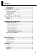
Contents Before Using the VC-30HD.................................................... 10 Supported Formats .................................................................................................... 10 About Rubber Feet ..................................................................................................... 10 Turning the Power On and Off.............................................. 11 Connecting the AC Adapter..........................................................................
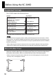
Before Using the VC-30HD Supported Formats The VC-30HD supports the following formats. fig.conversion-table.eps INPUT OUTPUT Component/HDMI i.LINK(Rear), USB 1080/59.94i, 50i, 23.98PsF 720/59.94p, 50p 576/50p, 480/59.94p HDV, MPEG-2 576/50i, 480/59.94i DV, MPEG-2 Composite/S-Video i.LINK (Rear), USB 576/50i, 480/59.94i DV, MPEG-2 i.LINK (Front) i.LINK (Rear), USB HDV, DV, MPEG-2 Thru Output * The output frame rate will be the same as the input frame rate.
Turning the Power On and Off Connecting the AC Adapter Place the AC adaptor so the side with the indicator (see illustration) faces upwards and the side with textual information faces downwards. * The indicator will light when you plug the AC adaptor into an AC outlet. fig.connect-PSB1U.
Turning the Power On and Off About Ground Terminal Depending on the circumstances of a particular setup, you may experience a discomforting sensation, or perceive that the surface feels gritty to the touch when you touch this device, video equipment connected to it, or the metal portions of other objects. This is due to an infinitesimal electrical charge, which is absolutely harmless. However, if you are concerned about this, connect the ground terminal (see figure) with an external ground.
Turning the Power On and Off About AUTO OFF The power to the VC-30HD is switched off automatically when four hours have elapsed with no input of video or audio signals (factory default). When this happens, the VC30HD does not function even though the POWER switch is at [ON]. To turn on the power again, first slide the POWER switch back to [OFF], then slide it to [ON] again. Deactivating AUTO OFF If automatic power-off is not needed, use the procedure described below to deactivate the feature. 1.
Names of Things and What They Do Front Panel fig.front-panel.eps 1 5 2 6 7 3 4 8 9 3. AUDIO INPUT indicators For information on button operations, refer to “Button operations” (p. 17). For information on source and output-format settings, refer to “Converting Signals” (p. 26). 1. VIDEO INPUT indicators These set and display the source. Use this button to switch the source. 2. OUTPUT FORMAT indicators These set and display the output format. Use this button to switch the output format.
Names of Things and What They Do 6. S-VIDEO connector Connect an S-Video source here. 7. HDMI connector Connect an HDMI source here. * Version 1.3, with Deep Color support HDCP (High-bandwidth Digital Content Protection) is not supported for HDMI input on the VC-30HD. 8. i.LINK input connector Connect an i.LINK source here. * If you plan on connecting a video deck or a computer to capture the output of the VC-30HD, use the rear i.LINK connector. The front i.LINK connector is reserved for i.
Names of Things and What They Do Rear Panel fig.rear-panel.eps 1 2 3 4 1. POWER switch This turns the VC-30HD’s power on and off. 2. DC IN connector This is for connecting the included AC adapter. 3. USB connector Connect a computer or other USB equipment as an output-destination device. 5 6 5. AUDIO IN selector switch This switches the mode of the AUDIO IN connectors. • ANALOG Both connectors (L and R) function, and the analog input mode is enabled.
Names of Things and What They Do About Button Operations The buttons switch the modes for [VIDEO INPUT], [OUTPUT FORMAT], and [AUDIO INPUT]. If the buttons are difficult to press, use a pen tip or the like to press them. 1. Check the current mode. Check the [VIDEO INPUT], [OUTPUT FORMAT], and [AUDIO INPUT] indicators. * The [OUTPUT FORMAT] indicators flash when an output format is incompatible with the input format. Selecting a supported output format makes the indicators light up steadily. fig.
Connecting External Equipment You can connect external equipment as shown below. * To prevent malfunction and/or damage to other devices, always turn off the power on all devices before making any connections. fig.connection-example.eps This unit is equipped with balanced XLR type jacks. Wiring diagrams for these jacks are shown below. Make connections after first checking the wiring diagrams of other equipment you intend to connect. fig.XLR-Jack.
Connecting External Equipment Connecting Video Sources Use appropriate cables and plugs to connect your video sources. For information on source selection, refer to “Converting Analog Input” (p. 26). Making a Component Connection When making a component connection, use all three [COMPOSITE/COMPONENT] connectors. Connecting a Video Camera Connect the component output from a video camera to the [COMPOSITE/COMPONENT] connectors on the front panel. fig.comp-connection-1.
Connecting External Equipment Making a Composite/S-Video Connection Making a Composite Connection Connect composite output from a video camera or video mixer to the [COMPOSITE/ COMPONENT] connector on the front panel. * When making a composite connection, use only the [VIDEO/Y] connector. * When BNC/RCA conversion is needed, use an adapter plug. No adapter plug is included with this product. fig.composite-connection.
Connecting External Equipment Making an HDMI Connection Connect a video camera or other device provided with HDMI output to the [HDMI] connector on the front panel. For information on the source selection, refer to “Converting HDMI Input” (p. 27). HDCP (High-bandwidth Digital Content Protection) is not supported for HDMI input on the VC-30HD. fig.HDMI-connection.eps Making an i.LINK Connection Connect a video camera or other device provided with i.LINK output to the [i.LINK] connector on the front panel.
Connecting External Equipment Connecting Audio Sources Making an Analog Connection Use analog connectors for the audio sources. For information on the source selection, refer to “Audio Source Settings” (p. 28). * When connection cables with resistors are used, the volume level of equipment connected to the inputs may be low. If this happens, use connection cables that do not contain resistors.
Connecting External Equipment Making a Digital Connection Use [AES/EBU] connector on the rear panel for your digital audio source. For information on the source selection, refer to “Audio Source Settings” (p. 28). * The standard supported by the VC-30HD is AES3 (16 to 24 bits, 32 to 48 kHz, 2 channels). fig.connect-AES-EBU.eps At this time, set the [AUDIO IN] selector switch to [AES/EBU TIMECODE]. * When this setting is in effect, you can input AES/EBU digital audio and a timecode simultaneously (p. 25).
Connecting External Equipment Connecting Output Equipment The format of i.LINK output and USB output cannot be set independently. The format set using [OUTPUT FORMAT] applies to both i.LINK and USB output. Connecting an i.LINK Device Connect a computer or video deck via i.LINK. Use an i.LINK cable to connect the computer or video deck to the [i.LINK OUT] connector on the rear panel. fig.connect-1394-output.eps Connecting a USB device Connect a computer via USB.
Connecting External Equipment Connecting a Timecode Source You can input a timecode from a source device simultaneously with digital audio. Use an XLR cable to connect the source device to the [TIMECODE] connector on the rear panel. * The standard supported by the VC-30HD is SMPTE 12M (LTC). fig.connect-TC-source.eps Audio LTC At this time, use the [AUDIO IN] selector switch to select [AES/EBU TIMECODE]. fig.select-AES-EBU.
Converting Signals Signals input to the VC-30HD are output from the i.LINK connector and USB connector on the rear panel. Use the button at [OUTPUT FORMAT] to select the output format. The VC-30HD does not support up/down scalling, interlace/progressive (I/P) conversion, or framerate conversion. The [OUTPUT FORMAT] indicators flash when the input and output formats are not compatible, such as the scenarios shown below. No output is possible while the [OUTPUT FORMAT] indicators are flashing.
Converting Signals Converting HDMI Input When HDMI has been selected for the source, you can select the settings described below for audio output. • [HDMI] Audio contained in the HDMI signal is output. • [HDMI+AUDIO] The audio signal contained in the HDMI signal is canceled, and the audio source selected using [AUDIO INPUT] is embedded to the output. L and R cannot be exchanged. fig.HDMI-convert.eps HDCP (High-bandwidth Digital Content Protection) is not supported for HDMI input on the VC30HD. i.
Converting Signals Audio Source Settings Use the button in the [AUDIO INPUT] section on the front panel and the selector switch on the rear panel to select the audio source. Possible selections are shown below. fig.audio-source-select.eps [RCA] + [ANALOG] The [AUDIO (L/R)] connectors on the front panel are enabled. [RCA] + [AES/EBU TIMECODE] The [AUDIO (L/R)] connectors on the front panel are enabled. You can also input timecode from the [TIMECODE] connector on the rear panel.
Appendices Main Specifications fig.specification-e1.eps Codec MPEG-2 Video, 8 bits, 4:2:0 1440 x 1080/59.94i, 50i, 23.98p (25Mbps) 1280 x 720/59.94p, 50p (18.3Mbps) 720 x 480/59.94p, 720 x 576/50p (18Mbps) HDV Video Format Audio Format MPEG-1 Audio Layer 2, 16 bits/48kHz, 2ch (384Kbps) DV Video Format 720 x 480/59.94i (NTSC), 720 x 576/50p (PAL) Audio Format Linear PCM, 16 bits/48kHz, 2ch MPEG-2 Video Format MPEG-2 Video, 8 bits, 4:2:0 1920 x 1080/59.94i, 50i, 23.98p (35Mbps) 1280 x 720/59.
Appendices fig.specification-e2.eps Input Connectors and Signals i.
Appendices About Remote Control Connecting a computer installed with the [VC-30HD RCS] dedicated remote-control software to the USB connector of the VC-30HD enables you remotely control the unit from your computer. Download [VC-30HD RCS] from the following Roland website. http://www.rolandsystemsgroup.net/ fig.RCS-screen.eps USB output to the connected computer is possible even while receiving remote control from the computer.
Appendices Dimensions fig.dimension.eps 41.8 11.8 189.6 7 Unit : mm 146 * When using the holes in the side panel to secure the unit in place, use screws measuring 3 mm in diameter and whose length is no more than 8 mm from the surface of the side panel.
Appendices Troubleshooting Can’t perform format conversion Is a format supported by the VC-30HD being input? The VC-30HD does not support up/down scalling, interlace/progressive (I/P) conversion, or frame rate conversion. The [OUTPUT FORMAT] indicators flash when the input and output formats are not compatible. No output is possible while the [OUTPUT FORMAT] indicators are flashing. For information on formats that can be input and output, refer to “Supported Formats” (p. 10).
For EU Countries This product complies with the requirements of EMC Directive 2004/108/EC. For the USA FEDERAL COMMUNICATIONS COMMISSION RADIO FREQUENCY INTERFERENCE STATEMENT This equipment has been tested and found to comply with the limits for a Class B digital device, pursuant to Part 15 of the FCC Rules. These limits are designed to provide reasonable protection against harmful interference in a residential installation.
For EU Countries For China
* 5 1 0 0 0 2 0 9 6 2 - 0 1 *