
Owner`s manual

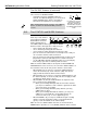
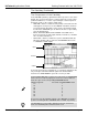
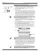
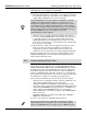
Table Of Contents
- Welcome!
- About this Application Guide
- I. The Components of a VM-7000 System
- II. Adding Options
- III. Listening to the VM-7000
- IV. Powering Up
- V. Initializing the System
- VI. The Level Meter Button as Home Page
- VII. Exiting Screens
- VIII. A New Kind of Bussing
- IX. What Do the Console’s Channel Strips Do?
- X. What Do the Console’s Faders Do?
- XI. The PARAM VIEW on Fader Buttons
- XII. Navigating the Display
- XIII. Adjusting Parameter Values
- XIV. SHIFT and the Green Button Labels
- XV. The CH EDIT Buttons
- XVI. The STATUS and MODE Buttons
- XVII. The Patchbay
- XVIII. Getting the First Signal
- XIX. Understanding Multi Outs
- XX. Routing a Signal to a Multi Out
- XXI. Using Flex Busses
- XXII. Routing Signals to an Internal Flex Bus
- XXIII. Routing Signals to an External Flex Bus
- XXIV. Routing Signals to a Pair of Flex Busses
- XXV. Understanding the Internal Effects
- XXVI. Setting Up a Send-and-Return Effect
- XXVII.Setting Up an Insert Effect
- XXVIII. Stereo-In, Stereo-Out Effects
- XXIX. Dual-Mono Effects
- XXX. Channel Dynamics Processing
- XXXI. Delay, Dynamics, EQ and Channel Libraries
- XXXII. Using a Memory Card
- XXXIII. Setting the VM-7000’s Clock
- XXXIV. Projects
- XXXV. Scenes
- XXXVI. Storing Libraries on a Memory Card
- XXXVII. Moving On...
12. Bring up Input Channel 1’s fader until it’s set to 100.You should now
be hearing the signal and seeing it in the stereo MAIN meter on the
display and the MASTER meter on the meter bridge.
Now let’s set the stereo placement of the signal in the main mix.
13. Press the CH PAN PARAM VIEW on Fader button. The faders move
to reflect the channels’ current pan settings and the INPUT CH
LEVEL/PAN display is presented. Most of the channels are set to
their center stereo positions, as reflected by the values shown under
the pan knobs on the display.
14. Move Channel 1’s fader to pan the signal in the main mix’s stereo
field. As you move the fader up and down, you should hear it
moving from speaker to speaker. When you’re done, place the
signal in the center—there’ll be a “C” under the displayed pan knob.
Before proceeding to the next section, press Input Channel 1’s green
(AUDIO) STATUS button to turn it off and remove Input Channel 1’s
signal from the main mix for now.
The 24 multi outs carry signals to the system’s R-BUS digital outputs,
SP/DIF and AES-EBU digital outputs, and ASSIGNABLE OUTs. Think of
the multi outs as wires connected directly to the system’s output jacks
and R-BUS output channels. When you want to route something to an
output—an individual signal, a Flex Bus, the main, cue or monitor mix—
you assign it to the multi out that’s connected to the desired output. Only
one thing can be assigned to each multi out at any given time.
Here’s how the 24 multi outs are connected to the system’s outputs:
•
R-BUS—There are 24 R-BUS channels. Therefore, Multi Outs 1-24
carry signals to R-BUS Channels 1-24, respectively.
• Analog—In addition to the VM-7200’s dedicated Flex Bus output
jacks (more on these later), both the VM-7200 and VM-7100 provide
eight analog ASSIGNABLE OUT jacks, labeled “1-8.” Multi Outs 17-
24 are connected to ASSIGNABLE OUTs 1-8, respectively.
•
SP/DIF—Multi Outs 21 and 22 carry signals to the SP/DIF DIGITAL
OUT A connectors.
• AES-EBU—Multi Outs 23 and 24 carry signals to the AES-EBU
DIGITAL OUT B connectors.
You can see all of this in the patchbay’s MULTI OUT box.
©2000 Roland Corporation U.S. Getting Started with the VM-7000 2796US, v1.0 Page 18
Getting the First Signal (Continued)
®ÂØÒňΠApplication Guide Getting Started with the VM-7000
The CH LEVEL/PAN screen and optional meter bridge are currently
showing the pre-EQ input level in Channel 1’s meter. If you’re ever
having trouble getting an input signal into the main mix, this can help
you troubleshoot your routing by showing whether or not the signal is
successfully reaching its channel strip in the first place. You can change
what the channel meters show by changing the POSITION setting on
the LEVEL METER screen, as described on p. 36 of the
VM-C7200/C7100 Owner’s Manual.
XIX. Understanding Multi Outs
Now you can see why they’re called “multi outs.” When you send a
signal to Multi Out 21, for example, it goes to three outputs: R-BUS
output 21, ASSIGNABLE OUT 5, and the left side of DIGITAL OUT A.