USER'S MANUAL Thank you very much for purchasing this product. To ensure correct and safe usage with a full understanding of this product's performance, please be sure to read through this manual completely and store it in a safe location. Unauthorized copying or transferral, in whole or in part, of this manual is prohibited. The contents of this document and the specifications of this product are subject to change without notice.
For the USA FEDERAL COMMUNICATIONS COMMISSION RADIO FREQUENCY INTERFERENCE STATEMENT This equipment has been tested and found to comply with the limits for a Class A digital device, pursuant to Part 15 of the FCC Rules. These limits are designed to provide reasonable protection against harmful interference when the equipment is operated in a commercial environment.
Contents Contents........................................................................................................................1 Chapter 1 Machine Highlights...........................................................................................5 Part Names and Functions............................................................................................6 Printer Unit..........................................................................................................................
Contents Disposing of Discharged Ink.............................................................................................................................70 Cleaning....................................................................................................................................................................72 About Care and Maintenance of Print Head................................................................................................
Contents Viewing the Automatic Environment Correction Function Settings............................................... 122 Performing Printing and Cutting Separately..............................................................123 To Perform Printing and Cutting Separately............................................................................................. 123 Printing with Crop Marks..................................................................................................................
Contents Chapter 7 Main Specifications.......................................................................................161 Printing/Cutting Area.................................................................................................162 Maximum Area.................................................................................................................................................... 162 Maximum Area When Using Crop Marks.............................................................
1 Contents..........................................................................................1 Part Names and Functions.............................................................6 Printer Unit....................................................................................6 Operation Panel............................................................................8 Menu List........................................................................................9 Main Menu......................
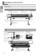
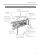
Part Names and Functions Printer Unit Highlights Machine 1 Front Front cover Keep this closed except when necessary, during when loading media. Cover L You remove this when you perform maintenance. Cover R You remove this when you perform maintenance. Operation panel P. 8, "Operation Panel" Drain bottle Loading lever You operate this when you load media. Rear Status LED This indicates the status of the machine's network feature. It lights up green when status is normal.
Part Names and Functions Front cover inside/print head periphery Grit rollers These rollers feed out media toward the front of the machine. Grit patterns These indicate the locations of the grit rollers. The pinch rollers must always be placed within the area indicated by each of these patterns. Left and right pinch rollers These clamp the media when the loading lever is lowered. Middle pinch rollers These are detachable and remountable pinch rollers.
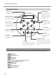
Part Names and Functions Operation Panel HEATER light This flashes while the media heating system is warming up, changing to a steadily lighted state when the preset temperature is reached. Display screen This displays various setting menus and other information. BASE POINT light This lights up when the base point (the outputstart location) has been set. PAUSE key This pauses printing operation. This lights up when operation is paused.
Menu List Main Menu 1 To the [CUTTING MENU] menu MENU MEDIA SETTING To the [NAME8] menu To the [SAVE] menu MENU PRESET PRESET LOAD LOAD NAME1 LOAD NAME8 To the [NAME1] menu To the [NAME8] menu PRESET SAVE SAVE NAME1 SET NAME NAME1 SAVE NAME8 SET NAME NAME8 To the [LOAD] menu To the [NAME1] menu To the [DETAIL SETTING] menu MENU ADJUST BI-DIR ADJUST BI-DIR TEST PRINT ADJUST BI-DIR SIMPLE SETTING SIMPLE SETTING 0 0 ADJUST BI-DIR DETAIL SETTING DETAIL SETTING TEST PRINT To the [SETTING] menu
Menu List Continue To the [MAINTENANCE] menu MENU SUB MENU Highlights Machine 1 SUB MENU EDGE DETECTION EDGE DETECTION ENABLE ENABLE SUB MENU SCAN INTERVAL SCAN INTERVAL OFF OFF SUB MENU VACUUM POWER VACUUM POWER AUTO AUTO SUB MENU FULL WIDTH S FULL WIDTH S FULL FULL SUB MENU ALTERNATION ALTERNATION DISABLE ENABLE SUB MENU PERIODIC CL. PERIODIC CL.
Menu List 1 Continue SYSTEM INFO. MODEL MODEL VS-640 SYSTEM INFO. SERIAL NO. SERIAL NO . ZS00001 SYSTEM INFO. INK INK E-SOL Max 4COLOR SYSTEM INFO. FIRMWARE FIRMWARE Ver.1.30 SYSTEM INFO. NETWORK NETWORK IP ADDRESS To the [MAC ADDRESS] menu IP ADDRESS 2 5 5. 2 5 5. 2 5 5. 2 5 5 IP ADDRESS 2 5 5. 2 5 5. 2 5 5. 2 5 5 NETWORK SUBNET MASK SUBNET MASK 2 5 5. 2 5 5. 2 5 5. 2 5 5 SUBNET MASK 2 5 5. 2 5 5. 2 5 5. 2 5 5 NETWORK GATEWAY ADDR. GATEWAY ADDR. 2 5 5. 2 5 5. 2 5 5. 2 5 5 GATEWAY ADDR.
Menu List Continue To the [TEST PRINT 2] menu To the [AUTO ENV. MATCH] menu MENU CUTTING MENU Highlights Machine 1 CUTTING MENU PRINT-CUT ADJ. PRINT-CUT ADJ. TEST PRINT To the [PRESET] menu PRINT-CUT ADJ. SETTING PRINT-CUT ADJ. TEST PRINT 2 To the [TEST PRINT] menu To the [TEST PRINT 2] menu CUTTING MENU CROP-CUT ADJ. CROP-CUT ADJ. TEST PRINT CROP-CUT ADJ. SETTING CROP-CUT ADJ.
Menu List Function Menu 1 To the [CUT CONFIG] menu FUNCTION BASE POINT BASE POINT ALIGN POINT 1 FUNCTION CLEANING CLEANING TEST PRINT To the [POWERFUL CL.] menu CLEANING NORMAL CL. CLEANING MEDIUM CL. CLEANING POWERFUL CL.
To Ensure Safe Use Highlights Machine 1 Improper handling or operation of this machine may result in injury or damage to property. Points which must be observed to prevent such injury or damage are described as follows. About WARNING and WARNING CAUTION Notices Used for instructions intended to alert the user to the risk of death or severe injury should the unit be used improperly.
To Ensure Safe Use Incorrect operation may cause injury. Keep children away from the machine. The machine includes areas and components that pose a hazard to children and may result in injury, blindness, choking, or other serious accident. Never operate the machine while tired or after ingesting alcohol or any medication. Operation requires unimpaired judgment. Impaired judgment may result in an accident.
To Ensure Safe Use Danger of electrical short, shock, electrocution, or fire Highlights Machine 1 WARNING WARNING Connect to an electrical outlet that complies with this machine's ratings (for voltage, frequency, and current). Incorrect voltage or insufficient current may cause fire or electrical shock. Ratings Side view of the machine Never use out of doors or in any location where exposure to water or high humidity may occur. Never touch with wet hands.
To Ensure Safe Use Important notes about the power cord, plug, and electrical outlet 1 Never allow to get wet. Never bend or twist with undue force. Never make hot. Never pull with undue force. Dust may cause fire. Never bundle, bind, or roll up. 17 Machine Highlights Never place any object on top or subject to damage.
To Ensure Safe Use Ink, cleaning fluid, and discharged fluid are flammable and toxic. Highlights Machine 1 WARNING CAUTION Keep open flame away from the work area. Ink and discharged fluid are flammable. Never store ink, cleaning fluid, or discharged fluid in any of the following locations.
To Ensure Safe Use This machine weighs 200 kg (441 lb.). Media weighs 40 kg (88 lb.). Install the machine in a location that is level, stable, and able to bear the weight of the machine. The total weight may reach over 200 kg (441lb.) for the 64-inch model (, 170kg (375lb.) for the 54-inch model, 150 kg (331lb.) for the 42-inch model, and 130 kg (287lb.) for the 30-inch model). Installation in an unsuitable location may cause a major accident, including tip over, fall, or collapse.
To Ensure Safe Use Warning Labels Highlights Machine 1 Warning labels are affixed to make areas of danger immediately clear. The meanings of these labels are as follows. Be sure to heed their warnings. Also, never remove the labels or allow them to become obscured. Caution: Pinching Hazard Be careful not to allow the fingers to become pinched when closing covers. Caution: Moving Print Heads The print heads inside the cover move at high speed and pose a hazard.
Pour utiliser en toute sécurité ATTENTION Utilisé pour avertir l'utilisateur d'un risque de décès ou de blessure grave en cas de mauvaise utilisation de l'appareil. Utilisé pour avertir l'utilisateur d'un risque de blessure ou de dommage matériel en cas de mauvaise utilisation de l'appareil. PRUDENCE * Par dommage matériel, il est entendu dommage ou tout autre effet indésirable sur la maison, tous les meubles et même les animaux domestiques.
Pour utiliser en toute sécurité L'utilisation incorrecte peut causer des blessures Highlights Machine 1 ATTENTION S'assurer de suivre les procédures d'utilisation décrites dans la documentation. Ne jamais permettre à quiconque ne connaît pas le fonctionnement ou la manutention de l’appareil de le toucher. L'utilisation ou la manutention incorrectes peuvent causer un accident. Garder les enfants loin de l'appareil.
Pour utiliser en toute sécurité PRUDENCE PRUDENCE 1 Attention : outil de coupe. Cet appareil contient un outil interne. Pour éviter les blessures, manipuler l'outil avec soin. Risque de décharge ou de choc électrique, d'électrocution ou d'incendie ATTENTION ATTENTION Brancher à une prise électrique conforme aux caractéristiques de cet appareil (tension, fréquence et courant). Une tension incorrecte ou un courant insuffisant peuvent causer un incendie ou un choc électrique.
Pour utiliser en toute sécurité ATTENTION Ne jamais placer d'objet inflammable à proximité de l'appareil. Ne jamais utiliser de produit inflammable en aérosol à proximité de l'appareil. Ne jamais utiliser l'appareil dans un endroit où des gaz peuvent s'accumuler. Une combustion ou une explosion pourraient se produire. Highlights Machine 1 Manipuler le câble d'alimentation, la fiche et la prise électrique correctement et avec soin.
Pour utiliser en toute sécurité Remarques importantes à propos du câble d'alimentation, de la fiche et de la prise électrique 1 Ne jamais laisser l'eau toucher le câble, la fiche ou la prise. Ne jamais plier ni tordre le câble avec une force excessive. Ne jamais chauffer le câble, la fiche ou la prise. Ne jamais tirer sur le câble ou la fiche avec une force excessive. La poussière peut causer un incendie. Ne jamais plier ni enrouler le câble.
Pour utiliser en toute sécurité L'encre, les liquides nettoyants et les liquides usées sont inflammables et toxiques Highlights Machine 1 ATTENTION Ne pas approcher une flamme nue de l'espace de travail. L'encre et les liquides usés sont inflammables.
Pour utiliser en toute sécurité Le poids de cet appareil est de 200 kg (441 lb.) Le poids du support est de 40 kg (88 lb.) Le déchargement et la mise en place doivent être faits par au moins 6 personnes on plus (, 4 personnes ou plus pour le modèle de 30 pouces). Les tâches qui exigent un effort trop grand si elles sont exécutées par un petit nombre de personnes peuvent être cause de blessures. La chute d'articles très lourds peut aussi causer des blessures.
Pour utiliser en toute sécurité Vignettes d'avertissement Highlights Machine 1 Des vignettes d'avertissement sont apposées pour qu'il soit facile de repérer les zones dangereuses. La signification des vignettes est donnée ci-dessous. Respecter les avertissements. Ne jamais retirer les vignettes et ne pas les laisser s'encrasser. Attention : Risque de pincement Faire attention de ne pas coincer les doigts pendant le chargement du support ou lors de la fermeture du couvercle.
Important Notes on Handling and Use This machine is a precision device. Handle carefully, and never subject the machine to impact or excessive force. Never needlessly put your hand or fingers inside the cover, the ink-cartridge ports, or other internal areas of the machine. Install in a suitable location. Install in a location having the specified temperature and relative humidity. Install in a quiet, stable location offering good operating conditions. The print heads are delicate.
30
Chapter 2 Basic Operation 2 Type of Media.............................................................................32 Usable Media..............................................................................33 Switch On!.....................................................................................34 Switch On!..................................................................................34 The Power-saving Feature (Sleep Mode) ................................34 Loading Media ..............
Prepare the Media Type of Media In this manual, the paper used for output is called “media.” There are the following main two media types used in this machine. Roll media: Media wound onto a paper tube Sheet media: Media not wound onto a paper tube such as standard-size media Various paper quality types of roll media and sheet media are selectable according your purpose. For detailed information about each media, contact your media supplier. Media is also available from our following website.
Prepare the Media Usable Media This machine cannot necessarily print every kind of media. When selecting media, be sure to carry out testing in advance to make sure that satisfactory printing quality is obtained. Size Width (For both Roll Media and sheet media) 2 A) Cuttable media thickness (For both Roll Media and sheet media) 0.08 mm to 0.22 mm (0.3 to 1 mil) (depending on media composition) B) Maximum media thickness (For both Roll Media and sheet media) Printing only:1.
Switch On! Switch On! WARNING Procedure Operation Basic 2 When output is not being performed, remove any loaded media or switch off the sub power. The continued application of heat at a single location may cause the release of toxic gases from the media or pose a fire hazard. Front cover Close the front cover. Turn on the main power switch. Main power switch Press the sub power button.
Loading Media Loading Roll Media CAUTION Roll media weighs about 40 kg (88 lb.). To avoid injury, handle with care. CAUTION Never load media that weighs over 40 kg (88lb.) for the 64-inch model (, 30 kg (66lb.) for the 54-inch model, and 25 kg (55lb.) for the 42-inch or the 30-inch model). The machine may fail to withstand the weight and tip over or cause the media to fall. Install the media to the media holder.
Loading Media Fit the paper tube (core) onto the end cap of the media holder [Left]. Do not secure the media holder now. Move the media holder [Right] and fit the media cap onto the paper tube core of the media. Fit it securely to prevent the media from easy loose. Operation Basic 2 Media holder [Left] Media holder [Right] End cap Install conforming to the procedures. Load the media while the left media holder is positioned close to the left edge, as shown in the figure.
Loading Media Hold the outer side of the media holder [Left] and position the left and right side edges of the media to match the grit patterns. When deciding the position, hold the both sides of media holders from the outer sides and move it. Do not hold the media directly to move. CAUTION Never attempt this operation while holding any location other than the one specified. The media may fall from the media holder, resulting in injury.
Loading Media 2. Pass the media through the printer and secure the media holders. Pass the leading edge of the media between the pinch rollers and the grit rollers. Front Pinch rollers Operation Basic 2 Grit rollers Pull out the media over the platen. Platen Check both edges of the media are placed on the grit rollers. Be sure to place the right edge of the media on the right end grit rollers.
Loading Media Place the left and right pinch rollers (affixed with blue stickers) on both edges of the media. Place them on the positions from the media edges by about 10 mm respectively. Right side pinch rollers (Blue sticker) Left side pinch rollers (Blue sticker) About 10 mm If you want to readjust the media position at this step, go back to the procedure 1 and redo the procedure 1..
Loading Media Hold the media at the center and pull it out, being sure to keep it straight and all areas of the media to be taut. Lower the loading lever to secure the media in place. Operation Basic 2 40 starts to flash, and then the screen shown in the figure appears.
Loading Media 3. Clamp the edges of the media with the media clamp. Move the left and right media clamps above the edges of the media. Line up the edges of the media with the centers of the holes of the media clamps. When you’re performing cutting only, never use the media clamps. P. 59, "Important Note on Cutting" 2 Close the front cover. When the front cover is closed, the print-head carriage moves and detects the width of media. This operation is called initialization.
Loading Media Loading the Sheet Media Procedure Move them to a location where they don’t disturb the media when the media is hung down from the rear of the machine. If they disturb the media, remove them with the shaft. For information on how to remove, refer to “Setup Guide.” Operation Basic 2 Move the media holders to the left and right. Loosen. Loosen. Pass the media through the printer and secure the media holders. Procedure 2.
Loading Media Lower the loading lever to secure the media in place. starts to flash, and then the screen shown in the figure appears. When you’re performing cutting only, never use the media clamps. P. 59, "Important Note on Cutting" 2 Move the left and right media clamps above the edges of the media. Line up the edges of the media with the centers of the holes of the media clamps. Close the front cover.
Loading Media Performing the Initial Adjustment (Correcting for Misalignment in Bidirectional Printing More Precisely) Perform the initial adjustment (correction for misalignment in bidirectional printing more precisely) of this machine. In the following case, perform this adjustment.
Loading Media NO.3 ‑ 6 NO.4 ‑ 4 Press to select a correction value of No.3 Press . Set correction values of No.4 to No.10. in the same manner. NO.9 ‑ 6 NO.10 ‑ 4 When correction value settings end, press Press . to go back to the original screen.
Setup of Media About [Media Setting] menu To ensure the optimal output according to the media size and type, various setting items are provided in this machine. However, it is hard work to perform these settings one by one referring to this document. So, this machine provides the [Media Setting] menu that guides these settings in the interactive mode. Using this menu, you can set all of the basic settings only by setting according to the instructions on the display.
Setup of Media DRYER OFF 40℃ Current preset Temperature temperature to be set Use to set the temperature. Recommended temperature: 40 degrees (104°F) Press to enable the setting. For the individual setting method of this setting item and the description, refer to p. 100, "Making the Temperature Setting for the Media Heating System." Procedure 3. Press during the setting. QUIT SETTING? YES [NO] Press Press to select [YES]. .
Setup of Media 4. Feed direction means the feed direction of the media. Perform the correction adjusting to the media in advance because horizontal stripes are more likely to occur during printing when the movement distance of the media changes subtly depending on the media’s thickness. Operation 2 Basic Perform the position correction of feed direction (Alleviate Horizontal Stripes). CALIBRATION [SET] NEXT Press Press to select [SET]. to enable the setting.
Setup of Media 5. Performing the correction for misalignment in bidirectional printing This machine prints by the bidirectional mode (in which the heads perform printing during both their outbound pass and return pass). This printing method is called “Bidirectional Printing.” This method offers the advantage of being able to shorten output times, but subtle misalignment occurs during the outbound and return passes. The procedure to correct this and eliminate misalignment is “Bidirectional Correction.
Setup of Media 6. Deciding to perform the setting for cutting or not CUT CONFIG [SET] NEXT [Only Printing] Press to select [NEXT]. Press to enable the setting. Go to Procedure10. [Print & Cut] Press to select [SET]. Press to enable the setting. Go to Procedure7. Operation Basic 2 7. Setting the blade force For high-quality cutting, perform a cutting test to check the cutting quality for the media and adjust the blade force. CUT FORCE [SET] NEXT Press Press to select SET].
Setup of Media CUT FORCE 50gf Current correction value 50gf Value to be set REDO ADJ. ? EXEC [COMPL] Use to adjust the blade force. If two shapes are peeled off together raise the blade force. If backing paper is cut too reduce the blade force. Press to enable the setting. Cut the test pattern again. Check the result. [Two shapes are peeled off separately] Press to select [COMPL]. Press to enable the setting. 2 Cut the test pattern again. Go back to the procedure and set again.
Setup of Media [Cutting position and printing position are aligned] Press to select [COMPL]. Press to enable the setting. CONTINUE ADJ. ? [EXEC] CANCE Go to Procedure9. [Cutting position and printing position are not aligned] Press to select [EXEC]. Press to enable the setting. The test pattern (P&C2) for setting the correction values is printed and cut. Go to Procedure . Operation Basic 2 When the left figure is displayed, press PLEASE INPUT ADJ. VALUES .
Setup of Media REDO ADJ. ? EXEC [COMPL] [Cutting position and printing position are aligned] Press to select [COMPL]. Press to enable the setting. Go to Procedure9. [Cutting position and printing position are not aligned] Press to select [EXEC]. Press to enable the setting. For the individual setting method of this setting item and the description, refer to p. 119, "Correcting Misalignment of the Printing and Cutting positions." 9.
Setup of Media [Cutting position and printing position are aligned] Press to select [COMPL]. Press to enable the setting. CONTINUE ADJ. ? [EXEC] CANCE Go to Procedure 10. [Cutting position and printing position are not aligned] Press to select [EXEC]. Press to enable the setting. The test pattern (C&C2) for setting the correction values is printed and cut. Operation Basic 2 When the left figure is displayed, press PLEASE INPUT ADJ. VALUES .
Setup of Media REDO ADJ. ? EXEC [COMPL] [Cutting position and printing position are aligned] Press to select [COMPL]. Press to enable the setting. Go to Procedure 10. [Cutting position and printing position are not aligned] Press to select [EXEC]. Press to enable the setting. For the individual setting method of this setting item and the description, refer to p. 128, "Correcting Misalignment for Printing and Cutting When Using Crop Marks." 10.
Setup of Media FEED FOR DRY 10min 10min Current setting Press Example of setting time (general guide): Setting after changed * The setting time varies according to the settings of type of media and printing quality. Output accompanying pull-back; use the middle pinch rollers; non-coated vinyl media about three minutes Operation 2 Basic to select the item. Press to enable the setting. Drying Time after Printing Set the drying time after the 1st page is printed.
Outputting Setting the Output-start Location You can set the output-start location at any location you prefer. (You can output if you do not set this.) Note, however, that this setting must be made for each individual page. Procedure Open the front cover. 2 Only cutting carriage moves. Printing area Output-start location Scan-direction start location Feed-direction start location When the location is set, press . FUNCTION BASE POINT When the left figure is displayed, press setting.
Outputting Printing Tests and Cleaning Before you carry out actual printing, we recommend performing a printing test to ensure no dot drop-out occurs. If dot drop-out occurs, perform cleaning of the print head (Normal Cleaning). How to Perform a Printing Test Procedure Operation Basic 2 Setting the Output-start Location P. 57, "Setting the Output-start Location" Press . FUNCTION CLEANING Press Press to display the left figure. . CLEANING TEST PRINT Press .
Outputting How to Perform a Normal cleaning Procedure . Press Press to display the left figure. , and then . CLEANING NORMAL Press . 2 Normal cleaning starts. CLEANING... >> CLEANING NORMAL When it finishes, the screen shown in the figure appears again. W1200mm SETUP SHEET Press to go back to the original screen Perform a printing test again to make sure the dot drop-out has been corrected. If the problem persists, try performing cleaning a second time.
Outputting When you’re performing cutting only using the roll media, never allow the media to hang down from the rear of the machine. (or set the [PREFEED] menu to “ENABLE.”) This prevents a motor error or fall of the roll because the media is pulled with excessive force. For the [PREFEED] menu, refer to p. 114, "Preventing Pulling of the Media with Undue Force When Performing Cutting Only." Turn the media by hand to pull out the necessary length from the roll.
Outputting Peel off the cut shapes to verify the cutting quality. [Two shapes are peeled off separately] Rectangle You do not need to perform the setting because the blade force is appropriate. Circle [Two shapes are peeled off together/backing paper is also cut] Go to the next Procedure to set the blade force. Setting the blade force. FUNCTION CUT CONFIG Press . CUT CONFIG FORCE Press . FORCE 50 gf Press to select the value.
Outputting Getting Ready to Receive Data from a Computer When p. 35, "Loading Media," p. 46, "Setup of Media" are completed, get ready to receive the data from a computer. CAUTION Procedure Operation Basic 2 Never touch the print heads while output is in progress. The print heads move at high speed. Contact may cause injury. Close the front cover. Make sure stays steadily lit. Wait until stays steadily lit. If the light does not come on, lower the loading lever.
Outputting Starting Output When the operation of p. 62, "Getting Ready to Receive Data from a Computer" is completed, you can start output. To output, the following procedure is required Creating Output Data Create the output data using the application software like Adobe Illustrator and like that. For information on how to create the data, refer to the documentation of your application software. Sending the Output Data to This Machine Using the Software RIP.
Outputting Pausing and Canceling Output You can pause and cancel printing before it finishes. We do not recommend resuming printing because horizontal stripes are produced at the place where output stopped. Procedure Operation Basic 2 Press before output finishes Press again to resume printing. This pauses printing operation. To cancel the output, go the next Procedure without pressing . When the screen shown in the figure appears, hold down for one second or longer.
Outputting Press . The media is cut off. Blade protector Blade protector 2 The media is fed You can make the setting in the software RIP for automatic media cutoff after printing or cutting has finished. For information on how to make the setting, refer to the documentation for the software RIP you're using. Cut-off Operations Be sure to detach the media clamps.
Switch Off Switch Off WARNING Procedure Operation Basic 2 When output is not being performed, remove any loaded media or switch off the sub power. The continued application of heat at a single location may cause the release of toxic gases from the media or pose a fire hazard. Switch off the sub power whenever output is finished. Hold down the sub power button for one second or longer. Raise the loading lever. Even except for switching off the power, raise the loading lever.
Chapter 3 Maintenance: For always using the printer in the best condition Checking for Remaining Ink and Replacing Cartridges................68 3 Maintenance Checking for Remaining Ink.......................................................68 How to Replace Ink Cartridges...................................................69 Maintenance that Should Be Performed Daily..............................70 Maintenance of Ink Cartridges...................................................
Checking for Remaining Ink and Replacing Cartridges Checking for Remaining Ink Procedure Press . Press appears. Press MENU INK REMAINING 1 5 2 6 3 7 4 8 several times until the screen shown on the left . indicates the amount of ink remaining. When there are more , the amount of ink remaining is larger. * The display shows an approximate guide to the amount of remaining ink. It may differ somewhat from the actual amount remaining.
Checking for Remaining Ink and Replacing Cartridges How to Replace Ink Cartridges When ink runs out, a warning beep sounds and printing pauses (unless the default settings have been changed). Pull out the empty cartridge and insert a new one. Printing resumes. SHAKE CARTRIDGE 12345678 Keep the labeled side face up. Insert and remove slowly, one at a time. Insert the new cartridge straight down from the top until you hear a warning beep sound.
Maintenance that Should Be Performed Daily Maintenance of Ink Cartridges SHAKE CARTRIDGE 1 2 3 4 5 6 7 8 When the message shown in the figure is displayed, remove the ink cartridge of the flashing slot number and shake it gently. To get the stable printing quality, shake the ink cartridge periodically to maintain the good ink condition. When the ink cartridge is reinserted into the original slot or is pressed, the message disappears. Shake it gently so that ink does not spatter.
Maintenance that Should Be Performed Daily EMPTY DRAIN BOTTLE When the screen shown on the left appears, detach the bottle, discard the discharged fluid to empty it. Upper limit Discard before this is reached. Before you detach the drain bottle, be sure to wait for the screen to display "EMPTY DRAIN BOTTLE." Failing to follow this procedure may cause discharged fluid to flow out of the tube and spill, soiling your hands or the floor.
Maintenance that Should Be Performed Daily Cleaning WARNING Never use gasoline, alcohol, thinner, or any other flammable material. Doing so may cause fire. CAUTION Before attempting cleaning, switch off the sub power and wait until the platen and dryer cool (approximately 30 minutes). Sudden movement of the machine may cause injury, or hot components may cause burns. Wipe away any buildup of ink or grime on the media path and other locations as daily cleaning.
Maintenance that Should Be Performed Daily About Care and Maintenance of Print Head Care of the print head is essential to ensuring optimal printing at all times. There are daily care and periodic care. Daily Care and Maintenance Normal cleaning It is recommended to perform the normal cleaning before daily operation. P.
When Normal Cleaning Is Not Effective Medium/ Powerful Cleaning When the problems such as dot drop-out are not cleared up by the "normal cleaning" (p. 58, “Printing Tests and Cleaning”), try the more forceful "medium cleaning." If the condition is not improved, try the even more forceful "powerful cleaning." Note, however, that the medium and powerful cleaning consumes more ink than normal cleaning, and too-frequent use may damage the print head itself. Avoid using it more than necessary.
Maintenance that Should Be Performed More Than Once a Month When Manual-Cleaning Becomes Necessary Perform the manual cleaning more than once a month. To keep the stable output condition at all times, perform the manual cleaning more than once a month. The manual cleaning takes approximately 10 minutes. The manual cleaning is recommended when the following symptoms occur.
Maintenance that Should Be Performed More Than Once a Month Manual Cleaning of Print Head Important Notes on This Procedure Before attempting this operation, remove any media. To prevent the heads from drying out, finish this procedure in 30 minutes or less. A warning beep sounds after 30 minutes. Never use any implement other than the included cleaning stick. Cotton swabs or other lintproducing items may damage the heads.
Maintenance that Should Be Performed More Than Once a Month When the screen shown on the left appears, open the cover L. OPEN COVER L Screw Cover L Hook 3 CUTTING RAIL Maintenance REMOVE Remove the cut rail. Press . Screw Cut rail CLOSE COVER L Close the cover L.
Maintenance that Should Be Performed More Than Once a Month CLOSE FRONT COVER Close the front cover. OPEN COVER L Open the cover L. FINISHED? Preparations are complete when this screen appears. 2. The print-head carriage moves to the left side of the machine, and then the screen shown in the figure appears. Remove cover R. Remove the cover R. Screw Maintenance 3 Hook Cover R 3. Touch the location shown in the figure to discharge any static electricity.
Maintenance that Should Be Performed More Than Once a Month Check that the cut rail has been detached. Perform cleaning in the sequence shown in the figure below. If the cut rail is not detached, close all the covers and restart the operation from the beginning. If you continue the operation as the cut rail remains attached, the print head might get broken. Be especially careful to clean away any fibrous dust (lint). Area to clean Area to clean Area to clean 3 Clean only the metal frame.
Maintenance that Should Be Performed More Than Once a Month Close the front cover. Press . The print-head carriage moves to the right side of the machine, and then the screen shown in the figure appears. OPEN COVER L Open the cover L. REPLACE CUT RAIL Replace the cut rail. Press . Maintenance 3 Screw Cut rail CLOSE COVER L Attach the cover L. Press . CLEANING... >> MAINTENANCE CLEANING 5. W1200mm SETUP SHEET Press to go back to the original screen.
When Problems Such As Dot Drop-out are Not Cleared Up When Problems Such As Dot Drop-out are Not Cleared Up When flaws in the dot pattern such as dot drop-out are not cleared up even after performing cleaning using the cleaning function (normal, medium, or powerful) or manual cleaning, perform the operation described below. A large amount of ink will be discharged during this operation.
When Problems Such As Dot Drop-out are Not Cleared Up SHAKE CARTRIDGE When the left figure is displayed, remove all the ink cartridges and shake them. Shake it gently so that ink does not spatter. Reinstall all the ink cartridges in the original slots. Press . The screen shown in the figure appears. EMPTY DRAIN BOTTLE CAUTION Be sure to discard the discharged ink at this step. A large amount of ink will be discharged during this operation. Be sure to discard the discharged ink at this step.
When Problems Such As Dot Drop-out are Not Cleared Up About [CIRCULATE INK] menu INK CONTROL CIRCULATE INK [CIRCULATE INK] [Ink Circulation] is the menu displayed only when the ink mode is in WMT. Use this menu only at the time of transfer. For more information on the operation at the time of transfer, refer to the “Setup Guide.
Replacing Consumable Parts Replacing the Wiper The wiper is a component that you use when cleaning the print head. When the screen displays a message like the one shown, it means the item needs to be replaced. Replace with new items. TIME FOR WIPER REPLACE Regarding the purchase of the wiper, contact your authorized Roland DG Corp. dealer. CAUTION 1.
Replacing Consumable Parts Touch the location shown in the figure to discharge any static electricity. FINISHED? 2. Replace the wiper. 3 Maintenance Preparations are complete when this screen appears. Detach the old wiper. Tweezers (included part) Pull up and out. Hook Detach the hook. Hitching the tweezers to the hole on the wiper makes the removal easier. Insert the new wiper. Place the inclined end on the back side.
Replacing Consumable Parts Attach the hook. Make sure to attach the hook. Otherwise it cases dot-drop out or else. Hook 3 Maintenance 3. Reattach the cover R, and quit the wiper replacement menu. Attach the cover R. Screw Cover R Hook Press . CLEANING... >> MAINTENANCE REPLACE WIPER 4. W1200mm SETUP SHEET After the process to quit the wiper replacement menu, the screen shown in the figure appears. Press to go back to the original screen.
Replacing Consumable Parts Replacing the Felt Wiper The felt wiper is a component that you use when cleaning the print head. When the screen displays a message like the one shown, it means the item needs to be replaced. Replace with new items. TIME FOR FELT REPLACE Regarding the purchase of the felt wiper, contact your authorized Roland DG Corp. dealer. CAUTION 1. Enter the felt wiper replacement menu. 3 When the message shown in the figure appears, press TIME FOR FELT REPLACE .
Replacing Consumable Parts Maintenance 3 Touch the location shown in the figure to discharge any static electricity. FINISHED? 2. Replace the felt wiper. Preparations are complete when this screen appears. Detach the old felt wiper. Tweezers (included part) Hook Pull up and out. Detach the hook. Hitching the tweezers to the hole on the felt wiper makes the removal easier. 88 Insert the new felt wiper.
Replacing Consumable Parts Attach the Hook. Make sure to attach the hook. Otherwise it cases dot-drop out or else. Hook Reattach the cover R, and quit the felt wiper replacement menu. Maintenance 3. 3 Attach the cover R. Screw Cover R Hook Press . CLEANING... >> 4. MAINTENANCE REPLACE FELT After the process to quit the felt wiper replacement menu, the screen shown in the figure appears. W1200mm SETUP SHEET Press to go back to the original screen.
Replacing Consumable Parts Replacing the Blade If the blade becomes dull, or if the edge of the blade is chipped, or if the blade quality is lowered, replace it with a new blade. 1. Maintenance 3 CAUTION Be sure to perform operations as specified by these instructions, and never touch any area not specified in the instructions. Sudden movement of the machine may cause injury. CAUTION Never touch the tip of the blade with your fingers. Doing so may result in injury.
Replacing Consumable Parts Replace the blade. Press this pin. Old blade Remove the old blade. Pin New Blades Install a new blade. Support the screw from below and insert the blade holder. Screw Insert until the collar is flush with the surface. 3. 4. Tighten the screw. Tug the blade holder upward to make sure it does not come loose. Quit the blade replacement menu. Close the front cover. Press . W1200mm SETUP SHEET Press to go back to the original screen.
Replacing Consumable Parts Replacing the Separating Knife If the separating knife becomes dull, replace it with the included replacement knife. 1. Maintenance 3 CAUTION Be sure to perform operations as specified by these instructions, and never touch any area not specified in the instructions. Sudden movement of the machine may cause injury. CAUTION Never touch the tip of the blade with your fingers. Doing so may result in injury. Replacing the Separating Knife Press . Press appears.
Replacing Consumable Parts Install a new knife. The knife is secured in place by the magnet. Magnet Positioning groove Slowly insert it into the groove. 3 Maintenance 3. Tighten the screw. Take care to ensure that the knife does not slip out of position at this time. Quit the blade replacement menu. Close the front cover. Press . W1200mm SETUP SHEET Press to go back to the original screen.
When Not in Use for a Prolonged Period Keep Performing Maintenance Switch On the Power Once a Month Switch on the sub power once a month. When you turn on the power, the machine automatically performs some operations such as those to keep the print head from drying out. Allowing the machine to stand completely unused for a prolonged period may damage the print head, so be sure to switch on the power to perform these automatic operations.
Chapter 4 Part of Practice Fully Utilizing Preset Function.......................................................96 Saving Various Settings as a Name Assigned Preset................96 Loading a Saved Preset.............................................................98 Fully Utilize the Media Heating System........................................99 What Is the Media Heating System?..........................................99 Making the Temperature Setting for the Media Heating System.........
Fully Utilizing Preset Function Saving Various Settings as a Name Assigned Preset Procedure Press . MENU PRESET Press Press twice to display the left figure. , and then . PRESET SAVE Press . SAVE NAME1 Press Press to select one of NAME1 through 8. to enable the setting. The present menu settings are saved. NAME S_ Press to enter a character. When a character is decided, press . The characters you can enter are "A" through "Z," "0" through "9," and the "-" character.
Fully Utilizing Preset Function [PREHEATING] P. 102, "Control of Media Heating System during Preheating" [DRYING TIME] P. 103, "Setting the Drying Time after Printing" [ADJUST BI-DIR SIMPLE SETTING] P. 104, "Correcting for Misalignment in Bidirectional Printing" [ADJUST BI-DIR DETAIL SETTING] P. 105, "Correcting for Misalignment in Bidirectional Printing More Precisely" [CALIBRATION] P. 105, "Alleviating Horizontal Bands and the Like (feed correction function)" [EDGE DETECTION] P.
Fully Utilizing Preset Function Loading a Saved Preset Procedure Press . MENU PRESET Press Press several times to display the left figure. twice. LOAD NAME1 Press Press to select a name to be called. to enable the setting. SETUP SHEET The settings are changed and the screen shown in the figure appears. Description This loads a saved preset. You can select any one of eight types of presets. (When no names have been assigned, you select from among NAME1 through NAME8.
Fully Utilize the Media Heating System What Is the Media Heating System? This machine is equipped with a media heating system that warms the media. You use this mainly to improve ink adhesion and also dry the ink. You can adjust the temperature settings to match the type of media and the printing speed. Print heater You use this mainly to improve ink adhesion. Dryer You use this to speed up drying of the ink. WARNING Remove any loaded media or switch off the sub power when printing is not being performed.
Fully Utilize the Media Heating System Making the Temperature Setting for the Media Heating System Procedure Press FUNCTION HEATER CONFIG Press Press HEATER CONFIG DRYER 34 C Press [DRYER] Press Current temperature of the dryer DRYER 35 C OFF Current preset temperature to select [PRINT] (print heater) or . to select a temperature. You can set to “OFF." When set to "OFF," the media heating system does not operate at all. Press to enable the setting.
Fully Utilize the Media Heating System Description By default setting, simply switching on the power does not make the media heating system warm up to the preset temperature. The temperature rises until preset temperature when the media is loaded correctly and lights up. You can also make this setting on the RIP software. When you have made the setting on the software, the software's setting is used.
Fully Utilize the Media Heating System Control of Media Heating System during Preheating Note: Preheating: State that the main power and the sub power are switched on and (state that media setup is not completed) is not lighted Procedure Press . MENU HEATER MENU Press Press several times to display the left figure. , and then . HEATER MENU PREHEATING Press . PREHEATING 30 C MENU Press to select setting.
Fully Utilize the Media Heating System Description "ENABLE" : media feed is performed until the trailing edge of the printing area is positioned on the dryer. The margin between the print-end position and the next print-start position is set to a value of 100 millimeters.
Fully Utilizing the Correction Function Correcting for Misalignment in Bidirectional Printing Procedure Press . MENU ADJUST BI-DIR Press Press several times to display the left figure. . ADJUST BI-DIR TEST PRINT Press . A test pattern is printed. When printing is completed, press order. SIMPLE SETTING -6 0 Press Press in this to select a correction value. to enable the setting. To decide a Correction Value Choose the value that produces the least misalignment of 2lines.
Fully Utilizing the Correction Function Correcting for Misalignment in Bidirectional Printing More Precisely When further correction is required, such as when adjustment made using [SIMPLE SETTING] does not enhance printing, use [DETAIL SETTING] to make corrections. For information on operations, refer to p.
Fully Utilizing the Correction Function Description The movement distance of media experiences subtle changes due to the thickness of the media and the temperature of the media heating system. When the movement distance becomes discrepant, horizontal stripes are more likely to occur during printing. We recommend performing correction to match the media you're using and the media heating system.
Accommodating to the Types and Condition of Media Adjusting Head Height to Match Media Thickness Procedure Press . MENU HEAD HEIGHT Press Press HEAD HEIGHT LOW LOW When the left figure is displayed, open the front cover. High Low several times to display the left figure. . Move the height-adjustment lever to adjust the head height. Moving the lever to "HIGH" makes a warning beep sound twice. Moving it to "LOW" makes the warning beep sound once.
Accommodating to the Types and Condition of Media Using Transparent Media Procedure Press . MENU SUB MENU Press Press several times to display the left figure. twice. EDGE DETECTION ENABLE DISABLE Press Press to select “DISABLE.” to enable the setting. SETUP SHEET The settings are changed and the screen shown in the figure appears. Description Practice Part of 4 This setting enables or disables detection of the leading and trailing edges of the media. It is normally set to "ENABLE.
Accommodating to the Types and Condition of Media Description You use this when ink dries poorly even when the media heating system is used. You can also make this setting on the RIP software computer. When you have made the setting on the computer, the computer's setting is used and the printer's setting is ignored. Default Setting [SCAN INTERVAL]: OFF Using the Media Easy to be Winkled/Hard to be Fed Procedure . MENU SUB MENU Press Press Press several times to display the left figure. .
Accommodating to the Types and Condition of Media Speeding Up Output for Narrow Media Procedure Press . MENU SUB MENU Press Press several times to display the left figure. . SUB MENU FULL WIDTH S Press Press several times to display the left figure. . FULL WIDTH S FULL OFF Press SHEET to select an item. "SHEET" matches the range of head movement to the width of the media. OFF OFF" matches the range of head movement to the output data.
Accommodating to the Types and Condition of Media Preventing Soiling of the Media and Dot Drop-out Procedure Press . MENU SUB MENU Press Press several times to display the left figure. . SUB MENU PERIODIC CL. Press Press several times to display the left figure. . PERIODIC CL . NONE 10 min Press PAGE to select an item. Automatic cleaning is performed every time before printing starts.
Accommodating to the Types and Condition of Media Using Sticky Media Procedure Press . MENU SUB MENU Press Press several times to display the left figure. . SUB MENU MEDIA RELEASE Press Press several times to display the left figure. . MEDIA RELEASE DISABLE ENABLE Press Press to select "ENABLE." to enable the setting. W1200mm SETUP SHEET Press to go back to the original screen. Description Some types of media may tend to stick to the platen.
Accommodating to the Types and Condition of Media Clamping the Nozzle Array to be Used (CMYKLcLm mode only) *CMYKLcLm Mode: State that six colors (cyan, magenta, yellow, black, light cyan and light magenta) are used in this machine. Procedure Press . MENU SUB MENU Press Press several times to display the left figure. . SUB MENU ALTERNATION Press Press several times to display the left figure. . ALTERNATION ENABLE DISABLE Press Press to select “DISABLE.” to enable the setting.
Fully Utilizing Cutting Function Hints and Tips for Cutting Setting Setting the [PREFEED] menu item to “ENABLE” makes the machine automatically feed out media and take it up again before cutting. This makes it unnecessary to run out media to the rear of the machine before the operation. P.
Fully Utilizing Cutting Function Fine-tuning the Cutting Conditions Procedure Performing the Cutting Test P. 60, "Setting The Cutting Test And The Blade Force"Procedure 1. When cutting of the test patterns is completed, press CUT CONFIG FORCE Press Press . . to select the set cutting condition. [Force] This sets the force (pressure) of the blade. (Default Setting 50gf ) [Speed] This sets the speed of cutting.
Fully Utilizing Cutting Function Evaluating the Results of a Cutting Test Check the shape of the test pattern. The cut shape is distorted. Decrease the value of [Speed]. Circle Rectangle Peel off the circle. The rectangle also peels off. Increase the value of [Force]. Some uncut areas remain. Decrease the value of [Speed]. Peel off the rectangle. The blade should leave faint traces on the backing paper. Do not change the value of [Force]. The blade trace is indistinct.
Fully Utilizing Cutting Function Accurately Adjusting the Cutting-in Amount When you want to perform accurate and fine adjustment of the cutting-in amount, such as when cutting media with thin backing paper, you can obtain good results by adjusting the tip of the blade. Turn the cap portion of the blade holder to adjust the amount of blade extension. Each indicator tick corresponds to 0.1 millimeters, and adjustment for 0.5 millimeters can be made by rotating the cap one full turn.
Fully Utilizing Cutting Function Performing Distance Correction During Cutting *When you’re performing printing followed by cutting, be sure to set the correction value to “0.00%.” Otherwise the printing and cutting positions may become misaligned Procedure Press . MENU CUTTING MENU Press Press Press to display the left figure. . twice. CUTTING MENU CALIBRATION Press . CALIBRATION FEED SETTING Press . FEED SETTING 0.00% 0.00% Practice Part of to select a correction value.
Fully Utilizing Cutting Function Correcting Misalignment of the Printing and Cutting Positions Note: When performing this setting, make sure to set the correction value of [CUTTING MENU CALIBRATION] to “0.00%.” P. 118, "Performing Distance Correction During Cutting" Procedure Make sure the [AUTO ENV. MATCH] menu item is set to "ENABLE." P. 122, "Viewing the Automatic Environment Correction Function Settings" Perform bidirectional adjustment. P.
Fully Utilizing Cutting Function To check the test pattern (P&C2) The point where the cutting line intersects the correction-value scale is the correction value. Check the scan direction and the [FEED] side respectively. Cutting line Scan direction Correctionvalue scale [FEED] side. For the figure, the correction value is “-0.3.” Cutting line Practice Part of 4 PRINT - CUT ADJ. SETTING Press Press F :- 0.30 S : 0.00 Press to select a correction value of [F] (feed direction of media).
Fully Utilizing Cutting Function Description You perform this when printing followed immediately by cutting yields positioning for printing and cutting that is slightly misaligned. You print alignment marks, perform detection of the printed marks, and correct the discrepancy. Subtle misalignment between the printing and cutting positions may occur due to the thickness of the media or the head height. We recommend making correction to match the media you're using.
Fully Utilizing Cutting Function Viewing the Automatic Environment Correction Function Settings The automatic environment correction function is the function that adjusts automatically to the optimal condition of this machine according to the operating environment (humidity and temperature). Performing automatic adjustment can reduce misalignment in the scanning direction (the direction of head movement) during printing or cutting. Normally set to “ENABLE.
Performing Printing and Cutting Separately To Perform Printing and Cutting Separately You can remove the printed media and then reload it and perform cutting. (Example: Perform lamination or other processing after printing, then reload the media and perform cutting.) Then, carry out alignment to prevent misalignment of the printing results and the cut lines. Perform this adjustment in the next Procedure. Procedure Printing with Crop Marks P.
Performing Printing and Cutting Separately Media Sizes Allowing Automatic Crop Mark Detection Crop marks Pinch rollers 90 mm (3.5 in.) or more 1.5 mm (about 0.06 in.) 22.5 mm (0.89 in.) Where to cut the media off 1.5 mm (about 0.06 in.) Printable area 22.5 mm (0.89 in.) 80 mm (3.2 in.) or more When you are printing with crop marks, set a margin of at least 90 mm (3.5 in.) before the next printstart position. You can set the margin value with the software RIP you're using.
Performing Printing and Cutting Separately Aligning Automatically and Cutting When you make the setting for reading crop marks when sending cutting data from the computer, alignment is performed with the presence or absence of crop marks determined automatically. For information on how to make the setting, refer to the documentation for the software RIP you're using. Points for Media Setting Place the crop marks on the blade protector. Crop marks Blade protector 4 Set to 5° or less.
Performing Printing and Cutting Separately If Automatic Alignment Cannot Be Performed CROPMARK ERROR NOT FOUND If the machine fails to detect the crop marks, the screen shown in the figure appears and operation stops. Press then the screen goes back to the previous screen. Reload the media, and then send the data again. Reload the media, and then send the data again.
Performing Printing and Cutting Separately Aligning Manually and Cutting Depending on the type of media, it may not be possible to detect crop marks automatically. When crop marks cannot be detected automatically, you perform alignment manually. 1. Set the base point. FUNCTION BASE POINT Press W1100mm B Press to display the left figure. 4 BASE POINT is set. Set the align points. Use to align the center of the blade with the location shown in the figure.
Performing Printing and Cutting Separately Repeat Procedure to to specify other align points as required. Send the cutting data and perform cutting. About Align Points The numbers for align points are determined with reference to the location of the base point. You cannot set an align point unless you specify a base point. Redoing the setting for the base point clears any align points that have been set.
Performing Printing and Cutting Separately Press Press CROP - CUT ADJ. TEST PRINT 2 to display the left figure. . The test pattern (C&C2) is printed and cut. To check the test pattern (C&C2) The point where the cutting line intersects the correction-value scale is the correction value. In this figure, the value is "-0.3." Use the same method to read the value on the [FEED] side. Cutting Scan line direction Correctionvalue scale [FEED] side. In this figure, the value is "-0.3.
Performing Printing and Cutting Separately Description Depending on the composition of the media, the positioning of printing and cutting may be misaligned even when you're using crop marks. Make corrections for misaligned printing and cutting for the media you're using. Default Setting [F] (feed direction): 0.00 mm [S] (scanning direction): 0.
Using Media Take-up System Use The Media Take-up System When The Output Accompanied With The Pull-back Operation is Performed Note: The media take-up system (hereinafter called take-up system) is optional part. Note: For information on how to assemble and install the take-up system, refer to the user’s manual of the take-up system. Note: For information on the output not accompanied with the pull-back operation, refer to the user’s manual of the take-up system.
Using Media Take-up System How to Output by Limiting Length (Roland VersaWorks) This section describes “how to output by limiting the length” using Roland VersaWorks (hereinafter RVW). For information on the detail usage of RVW, refer to the user’s manual of RVW. Procedure Open "Que Properties" window (or "Job Setting" window) Select the input folder to be used. "Que Properties" window (The setting item and the method in "Job Setting" window are the same as this procedure.
Chapter 5 To Administrators Output Operation Management..................................................134 Printing a System Report..........................................................134 Determining What Happens When Ink Runs Out.....................134 Displaying the Amount of Media Remaining.............................135 Making Sure to Verify the Setting for the Amount Remaining Every Time the Media Is Changed.....................................................
Output Operation Management Printing a System Report This prints system information, including a list of setting values. Procedure Press . MENU SUB MENU Press Press several times to display the left figure. . SUB MENU SYSTEM REPORT Press Press several times to display the left figure. . Press to go back to the original screen. Start printing.
Output Operation Management Description When "STOP" is selected, printing pauses and so colors may be uneven. Ensure a sufficient amount of remaining ink before you begin printing. When "CONT" is selected, printing does not stop even if ink runs out completely. To replace the cartridge, wait until printing ends or press to pause printing. Default Setting [EMPTY MODE]: STOP Displaying the Amount of Media Remaining You can display how much of the media in use is left.
Output Operation Management Making Sure to Verify the Setting for the Amount Remaining Every Time the Media Is Changed SET LENGTH Set to display 0.0 m 25.0 m every time when a media is changed. Procedure Press . MENU SHEET REMAIN Press Press Press twice to display the left figure. . twice. SHHET REMAIN AUTO DISPLAY Press . AUTO DISPLAY DISABLE ENABLE Press Press to select "ENABLE". to enable the setting. If you set to "ENABLE," you must set the [EDGE DETECTION] menu to "ENABLE.
Output Operation Management Printing the Amount of Remaining Media This prints the amount of media remaining that is displayed at the top menu. Procedure Press . MENU SHEET REMAIN Press Press twice to display the left figure. . SHHET REMAIN PRINT MEMO Press . W1200mm SETUP SHEET Press to go back to the original screen. Start printing. Description You use this when you want to make a record of the remaining length of the media now in use.
System Management of Printer Setting for the Menu Language and the Units of Measurement This sets the language and units of measurement displayed on the display screen of the operation panel. Procedure Hold down and switch on the sub power. Use Press LENGTH UNIT INCH mm TEMP. UNIT C Use length. Press to select the display (menu) language. to enable the setting. to select the measurement unit for to enable the setting. Use to select to the measurement unit for temperature.
System Management of Printer Deactivating the Sleep Mode (Power Saving Function) Procedure Press . MENU SUB MENU Press Press several times to display the left figure. . SUB MENU SLEEP Press Press several times to display the left figure. , , and then . Press to select "DISABLE." to enable the setting. Press to go back to the original screen.
System Management of Printer Viewing Information about the System of This Machine Note: For information on how to set up a network, refer to "Setup Guide." Procedure Administrators To 5 140 Press MENU SYSTEM INFO. . Press several times to display the left figure. You can view the following information. [MODEL]: Model name [SERIAL NO.
System Management of Printer Returning All Settings to Their Initial Values This menu returns all settings to the same as their factory defaults. However, the settings for [MENU LANGUAGE], [LENGTH UNIT], and [TEMP. UNIT] are not returned to the factory defaults. Procedure Press . MENU SUB MENU Press Press several times to display the left figure. . SUB MENU FACTORY DEFAULT Press Press several times to display the left figure. to execute.
Administrators To 5 142
Chapter 6 Read this chapter whenever you face a problem. (FAQ) Printer Does Not Start Up!..........................................................144 The Printer Unit Doesn't Run....................................................144 The Media Heating System Doesn't Warm Up.........................145 Cannot cut off the media..........................................................145 Attractive Printing or Cutting is Impossible…..............................
Printer Does Not Start Up! The Printer Unit Doesn't Run Is the power switched on? Switch on the printer's main power, then press the sub power switch and make sure the sub power switch lights up. P. 34, “Switch On!” Is illuminated? Output is not performed when is not illuminated. Lower the loading lever. P. 62, "Getting Ready to Receive Data from a Computer” Is the front cover open? Close front cover, cover L and cover R.
Printer Does Not Start Up! Is the network routing appropriate? Try connecting the computer and the machine to the same hub, or connecting them directly using a crossover cable. If this makes it possible to perform output, it means the problem is in the network itself. Are the network settings correct? If the cable connections are secure and no problem is found in the network itself, make sure that the IP address and other such settings are appropriate.
Attractive Printing or Cutting is Impossible… Printed Results Are Coarse or Contain Horizontal Stripes Does the print head show dot drop-out? Carry out a printing test and make sure no dot drop-out occurs. If dot drop-out is present, perform head cleaning. P. 58 "Printing Tests and Cleaning," p. 74, "When Normal Cleaning Is Not Effective" Is the head height appropriate? Printing when the [HEAD HEIGHT] menu item is set to "HIGH" is coarser than when set to "LOW.
Attractive printing or cutting is impossible… Is the media loaded and set up correctly? If the media is not loaded and set up correctly, media feed may not be smooth, or printing may be adversely affected. Make sure the media is loaded and set up correctly. P. 151, "Media Feed is Not Smooth" Are the settings for the [PRESET] menu item appropriate? If the settings selected with the [PRESET] menu item are not suitable for the type of media, printing may be adversely affected.
Attractive Printing or Cutting is Impossible… The Media Becomes Soiled When Printed Does the print head contact the media? The height of the print head may be too low. Also, if the media is not loaded and set up correctly, it may wrinkle or come loose and strike the heads. P. 107, "Adjusting Head Height to Match Media Thickness," p. 151, "Media Feed is Not Smooth" Is the print head dirty? The following may cause ink to drip on the media during printing. Buildup of fibrous dust (lint) around the heads.
Attractive printing or cutting is impossible… Are you using media that exhibits large expansion and contraction? When you're performing printing followed immediately by cutting, misalignment occurs if the media expands or contracts. If this happens, try performing printing with crop marks, then setting the base point and one or more align points and performing cutting. This corrects for expansion and contraction of the media. Is [AUTO ENV.
Media Jam Occurs! The Media Jams If an error message is displayed because the media has jammed, immediately correct the problem. Failure to do so may damage the print head. P. 159, [MOTOR ERROR TURN POWER OFF] Is the media warped or wrinkled? Many factors can cause warping or wrinkling. Refer to the following and correct the problem. P. 151, "Media feed is not smooth" Is the height of the print head too low? Try raising the heads higher.
Media Feed is Not Smooth A variety of problems can occur if the media feed is not smooth. This can cause such problems as poor printing quality, contact with the media by the print head, misaligned positioning, or media jams. Take action as follows. Media Wrinkles or Shrinks Is the media loaded and set up straight and securely? Feed is not smooth when the media is not straight or is tensioned unevenly on the left and right. Reload the media. P.
Media Feed is Not Smooth Media Feed Is Not Straight Is the media loaded and set up straight and securely? Feed is not smooth when the media is not straight or is tensioned unevenly on the left and right. Reload the media. P. 46, “Setup of Media” Media Feed Is Not Smooth Do the media or the shafts strike some other object? Make sure the media and the shafts do not touch anything else. This may affect output, even when feed appears to be smoothly P.
Print Head Stops Moving. Why? If the print-head carriage stops over the platen, take action immediately to prevent the heads from drying out. What to Do First Switch the sub power off, then back on again. If the media is jammed, then also remove the media. If the print-head carriage move to the standby position (inside the side cover), it means the operation has ended successfully.
Print Heads Stops Moving. Why? Gently move the print head to the standby position. Stopping at the place where the audible click is heard locks the print head in place. Gently apply pressure from the right side to make sure the heads don't move to the left. If the print head moves to the left, again move them slowly by applying pressure from the left side and make sure they lock in place.
A Message Appears These are the main messages that appear on the machine's display to prompt correct operation. They do not indicate any error. Follow the prompts and take action accordingly. [1 ■ 2 ■ 3 ■ 4 ■ 5 ■ 6 ■ 7 ■ 8 ■] Only a small amount of ink remains. Replace the cartridge indicated by the flashing number with a new cartridge. [PRESS THE POWER KEY TO CLEAN] This appears when the machine has been unused for about one month. Switch on the sub power once a month. P.
A Message Appears [OPEN THE VALVE] Open the valve. The valve described here is the part you handle when you clean Heads to perform the first ink filling after purchasing this machine. Do not adjust this part except when you fill ink for the first time. If you try to close the valve in an undesirable manner, it may cause troubles including NG ink discharge.
An Error Message Appears This describes the error messages that may appear on the machine's display, and how to take action to remedy the problem. If the action described here does not correct the problem, or if an error message not described here appears, contact your authorized Roland DG Corp. dealer . [ALIGN POINT POSITION INVALID] An attempt was made to set an align point at a location where the setting cannot be made.
An Error Message Appears [TEMPERATURE IS TOO HIGH **°C] The temperature of the location where the machine is installed has risen above the ambient temperature at which the machine can operate. Operation cannot be continued. Switch off the sub power. The displayed temperature is the current ambient temperature of the installation location. Bring the installed location to a temperature at which operation is possible (15 to 32°C) and allow the machine to come to room temperature, then turn on the power.
An Error Message Appears [PINCHROLL ERROR INVALID LEFT POS] The left pinch roller is positioned at a location where it does not pinch the media. Raise the loading lever and move the left pinch roller to the correct location. P. 35, “Loading Media” [PINCHROLL ERROR INVALID RIGHT POS] The right pinch roller is positioned at a location where it does not pinch the media. Raise the loading lever and move the left pinch roller to the correct location. P.
An Error Message Appears The media was pulled with excessive force. Excessive tension was applied to the media, and additional action is necessary to recover from this state. First, move the loading lever to the rear and adjust the media to create a small amount of slack, then switch on the sub power.
Chapter 7 Main Specifications Printing/Cutting Area...................................................................162 Maximum Area..........................................................................162 Maximum Area When Using Crop Marks.................................162 The Media-cutoff Location During Continuous Printing............163 About the Blade..........................................................................164 Locations of the Power Rating and Serial Number Labels.........
Printing/Cutting Area Maximum Area The printing or cutting area along the horizontal plane (the direction in which the carriages move) is determined by the position of the pinch rollers. Max. 1,600 mm (64-inch model) Max. 1,364 mm (54-inch model) Max. 1,064 mm (42-inch model) Max. 736 mm (30-inch model) 90 mm Printing or cutting area Max. 24,998 mm 10 mm 1.5 mm 1.
Printing/Cutting Area The Media-cutoff Location During Continuous Printing When a media-cutoff command is sent from the computer, the cutoff location on the media is as shown in the figure below.
About the Blade The cutting conditions and the service life of the blade change according to the media and the operating environment, even when you're using identical blades. The service life also differs according to the type of blade. A rough guide is shown below. Blade Media Blade force Amount of blade offset Blade life* (general guide) ZEC-U1005 General signage vinyl 50 to 150 gf 0.25 mm 8000 m ZEC-U5025 General signage vinyl 30 to 100 gf 0.
Locations of the Power Rating and Serial Number Labels Serial Number This is required when you seek maintenance, servicing, or support. Never peel off the label or let it get dirty. Power Rating Use an electrical outlet that meets the requirements for voltage, frequency, and amperage given here.
Specifications Printing technology Media VS-420 VS-300 210 to 1,371 mm (8.3 to 54 in.) 182 to 1,071 mm (7.2 to 42.2 in.) 182 to 762 mm (7.2 to 30 in.) 210 to 1,625 mm (8.3 to 64 in.) Thickness Maximum 1.0 mm (39 mil) with liner, for printing Maximum 0.4 mm (16 mil) with liner and 0.22 mm (9 mil) without liner, for cutting Roll outer diameter Maximum 210 mm (8.3 in.) Roll weight Max. 40 kg (88 lb.) Core diameter(*1) 76.2 mm (3 in.) or 50.8 mm (2 in.) Max. 30 kg (66 lb.) Max. 1,346 mm (53 in.
Specifications *1 Note: The media holder of this machine is exclusive use for the media of paper tube (core) inner diameter 3 inches. To use 2 inches media, the optional media flanges are required. *2 The length of printing or cutting is subject to the limitations of the program. *3 Media type: Media specified by Roland DG Corp. (Cutting only) Temperature: 25°C (77°F), humidity: 50% Roll media must be loaded correctly. Applicable when all pinch rollers available to the media width are used.
168
169
170
171
172
This product is using GNU General Public License (GPL) / GNU Lesser General Public License (LGPL) software. You have the right to acquire, modify, and distribute the source code for this GPL/LGPL software. You can obtain the GPL/LGPL source code used in this product by downloading it from the following website. URL: http://www.rolanddg.com/gpl/ RolandDG Corp. has licensed the MMP technology from the TPL Group.