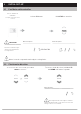
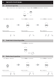
AUTOMATE ™ ARC ™ CORD LIFT MOTORS Part number Description MT01-3101-069001 Cord Lift DCRF Motor with extended P1 Button - 0.6N/34 433 MHZ BI-DIRECTIONAL ELECTRONIC LIMIT SELECTABLE RPM FAVORITE POSITION LEVEL CONTROL AUTOMATE™ | ARC™ Cord Lift motors enable motorized function of shades utilizing cord take up systems. The Leveling Control allows for precise positioning of individual or multiple shades ensuring perfect alignment every time.
CONTENTS 1 P1 BUTTON FUNCTIONS 4 1.1 Motor State Test 4 1.2 Motor Configuration Options 4 2 5 INITIAL SET-UP 2.1 Pair Motor with controller 5 2.2 Check motor direction 5 2.3 Set limits 6 3 7 ADJUSTING LIMITS 3.1 Adjust upper limit 7 3.2 Adjust lower limit 7 4 8 ADDING OR REMOVING CONTROLLERS AND CHANNELS 4.1 Using motor P1 button 8 4.2 Using a pre-existing controller 8 5 9 FAVORITE POSITIONING 5.1 Set favorite position 9 5.2 Send shade to favorite position 9 5.
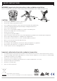
SAFETY INSTRUCTIONS WARNING: Important safety instructions to be read before installation. Incorrect installation can lead to serious injury and will void manufacturer’s liability and warranty. CAUTION • • • • • • • • • • • • • • • • • Do not expose to moisture or extreme temperatures. Do not allow children to play with this device. Use or modification outside the scope of this instruction manual will void warranty. Installation and programming to be performed by a suitably qualified installer.
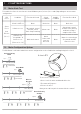
1 P1 BUTTON FUNCTIONS 1.1 Motor State Test This table describes the function of a short P1 button press/release(<2 seconds) depending on current motor configuration. P1 Press Short Press then Release (<2 sec) Condition Function Achieved Visual Feedback Audible Feedback Function Described If limit is NOT set None No Action None No Action If limits are set Operational control of motor, run to limit.
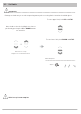
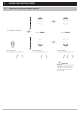
2 INITIAL SET-UP 2.1 Pair Motor with controller Select channel on controller. Activate P1 button Hold STOP on controller (Disregard if using single channel controller) IMPORTANT Motor Response Consult user manual for your controller for information on selecting channel. Motor Response RELEASE P1 Motor is now in setup mode and ready for setting limits. 2.2 Check motor direction To check travel direction of shade, press UP or DOWN on controller.
2.3 Set limits IMPORTANT Damage to shade may occur when operating motor prior to setting limits. Attention should be given. To save upper limit, hold UP and STOP. Move shade to the desired highest or lowest position by pressing the UP or DOWN buttons on controller. To save lower limit, hold DOWN and STOP. Quick Press = Step Long Press = Continuous Travel Motor Response Approx.
3 ADJUSTING LIMITS 3.1 Adjust upper limit Hold UP and STOP on Controller until the motor responds. Motor Response Move shade to the desired upper position by pressing the UP or DOWN button. To save upper limit, hold UP and STOP until the motor responds. Motor Response SECS Approx. 3.2 Adjust lower limit Hold DOWN and STOP on controller. Move shade to the desired lowest position by pressing the UP or DOWN button Motor Response Approx. To save lower limit, hold DOWN and STOP.
4 ADDING OR REMOVING CONTROLLERS AND CHANNELS 4.1 Using motor P1 button Activate P1 button Hold STOP on controller to add or remove Motor Response Motor Response RELEASE P1 4.2 Approx. Using a pre-existing controller A= Existing controller or channel (to keep) B= Controller or channel or add or remove Press P2 on existing controller. Motor Response Press P2 on existing controller.
5 FAVORITE POSITIONING 5.1 Set favorite position Move shade to the desired position by pressing the UP or DOWN button on the controller. Press P2 on controller. Motor Response 5.2 Press STOP on controller. Press STOP on controller. Motor Response Motor Response Send shade to favorite position Hold STOP on controller. Approx. 5.3 Delete favorite position Press P2 on controller. Motor Response Press STOP on controller. Press STOP on controller.
6 ADJUSTING MOTOR SPEED 6.1 Increase or decrease motor speed Press P2 on controller. Motor Response Press DOWN Motor Response Press DOWN Motor Response IMPORTANT If motor does not react to speed adjustment, the maximum or minimum speed has already been reached.
7 TILT & ROLLER MODE 7.1 Enter tilt mode Hold UP and DOWN on controller. Motor Response Press STOP Motor Response Approx. 5 SECS For slat adjustment on Venetians. 7.2 Enter roller mode (Default) Hold UP and DOWN on controller. Motor Response Press STOP Motor Response Approx.
8 SLEEP MODE 8.1 Enter sleep mode Sleep mode is utilized to prevent a motor from moving during shipping of a fabricated shade. Activate P1 button Motor Response Approx. 6 SECS Motor Response RELEASE P1 8.2 Exit sleep mode Exit sleep mode once shade is installed. PRESS & RELEASE P1 button on motor head. Motor Response Approx.
9 SOFT STOP ON/OFF 9.1 SOFT STOP ON Motor must be in fastest speed to turn Soft Stop ON. Press P2 on controller. Motor Response 9.2 Press UP on controller. Motor Response Press UP on controller. Motor Response SOFT STOP OFF Motor must be in slowest speed to turn Soft Stop OFF. Press P2 on controller. Motor Response Press DOWN on controller. Press DOWN on controller.
10 BATTERY CHECK FUNCTION 10.1 Send Shade to battery charge level Shade must be at Upper Limit. Hold UP Upper Limit Lower Limit Motor Response Approx. 5 SEC Shade must be at Upper Limit Hold UP for Approx.
11 TROUBLESHOOTING Problem Motor is not responding Unable to adjust or set limits. Cause Remedy A / C Adapter not plugged in. Check motor to power cable connection and AC plug. Battery in battery pack is depleted Replace 8xAA alkaline batteries. Power failure. Check power supply to motor is connected and active Transmitter battery is discharged Replace battery Battery is inserted incorrectly into transmitter. Check battery polarity Radio interference/shielding.
U.S. Radio Frequency FCC Compliance This device complies with Part 15 of the FCC Rules. Operation is subject to the following two conditions:(1) This device may not cause harmful interference, and (2) This device must accept any interference received, including interference that may cause undesired operation. This equipment has been tested and found to comply with the limits for a Class B digital device, pursuant to Part 15 of the FCC Rules.