
Owner's Manual


DESCRIPTION
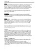
FRONT PANEL
Mic 1, 2: Adjust the level of signal from the corresponding Mic Input.
TONE 1, 2: Adjusts the frequency content of the microphone signal in the chan-
nel. When the control is turned counter-clockwise, the high frequencies are cut,
when the control is turned clockwise, the low frequencies are cut.
Source 1 - 3: Adjust the volume of input from the RCA Source Inputs.
IN 3: 1/8” (3.5 mm) Input jack - parallels the rear panel Source 3 Input.
Bass: Adjusts the low frequencies of the Source 1 and 2 signals only.
Treble: Adjusts the high frequencies of the Source 1 and 2 signals only.
Left / Right Output: Adjusts that channel’s output level
Right/Left Clip: LEDs indicating clipping in the indicated MA2152 ampli er side.
Protect: Indicates that the ampli er has reached overload, and the MA2152 will
need to be turned o , and restarted.
Power: LED indicating power is applied to the MA2152 and the unit is on.
REAR PANEL
IEC Power Input / Fuse Holder: Connects to the enclosed IEC power cable.
Please replace fuse only with recommended rating.
4 - 8 Ohm / 25 Volt Output: The two red banana jacks are used when the
MA2152 is in Bridge/Mono, or 70V mode.
RECORD OUT: Stereo RCA jacks, contains all mixed signals before the Master
Level controls.
SOURCE INPUTS: Stereo RCA jacks, Channels 1 - 3, for connection to stereo
sources such as AM/FM tuners, cassette players, cd players, or video players.
LEFT/RIGHT AMP INSERT: 1/4” Tip-Send, Ring-Return insert jack.
DIP SWITCH: Contains the small switches for engaging Mic 1, 2 phantom power,
Source 3 Stereo or Mono, the priority (Talk Over) functions, and the Mono/Stereo
select.
MICROPHONE ONE and TWO: Balanced XLR inputs to be connected to dynam-
ic or condenser microphones.
BRIDGE SWITCH: This switch selects the output con guration; Bridge Mono, or
Stereo / Dual Mono.