
Quick-Start Guide


1/8”
OFF=UP
ON=DOWN
www.rolls.com
+
-
VDC
RM424
4 Zone Mixer
ZONE 1
ZONE 2
TALK OVER ZONE ASSIGNMENT
PHANTOM POWER
ZONE
1
2
ZONE
1
2
ZONE
1
2
ZONE
1
2
MIC/LINE
MIC/LINE
INPUT LEVEL
MIC
LINE
PS27s
ZONE 3
ZONE 4
HEADPHONE
3
4
34
34
3
4
MONITOR
CHANNEL 4
CHANNEL 3
SERIAL NUMBER
REMOTE VOLUME
OUTPUT 3
OUTPUT 2
OUTPUT 1
OUTPUT 4
ZONE FOUR ZONE THREE ZONE TWO
ZONE ONE
3
4
MONITOR
MONITOR
MONITOR
MONITOR
MIC/CHANNEL 2
MIC 1
MIC/CHANNEL 2
MASTER VOLUME
1
2
3
4
MIC 1
+15
WIPER
COMM. +15
WIPER
CH.4
CH.3
REMOTE VOLUME
+15
WIPER
COMM. +15
WIPER
CH.2
CH.1
IN
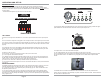
The remote volume section on the back of the
RM424 is designed to enable the installer the ability
to install remote volume controls for the various
zones of the RM424. Follow the silk screening of the
unit for exact channel information.
MIC/CHANNEL 2
is a single input
channel that
can be XLR
input or an RCA
input.
Channel 3
and 4 inputs
are line level
RCA’s.
The MASTER VOLUME
controls on the front of
the RM424 function just
as the name implies.
The MONITOR section of
the RM424 is designed to
be able to monitor a signal
before it is sent to a zone.
PHANTOM POWER and Talk Over Zone Assignment,
See page 5 of this manual.
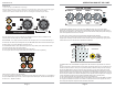
The front panel LEVEL and
ZONE switches are the
same for all channels.
Simply activate the appro-
priate switches to send that
channels information to the
required output zone.
The output XLR’s 1-4 are line level balanced outputs.
MIC 1 XLR input
switchable mic
or line level.